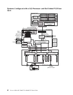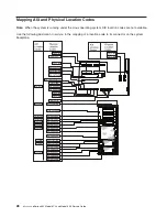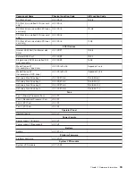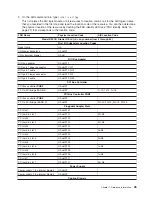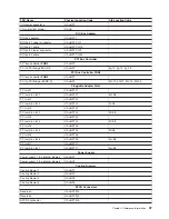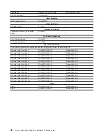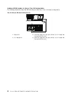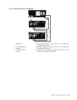
Component Name
Physical Location Code
AIX Location Code
Notes:
1. The physical location code for the PCI slots, when empty, uses the P1/Ix notation, where the ’/’ identifies an
integrated device (in this case the empty slot). A PCI device plugged into the slot uses the P1-Ix notation, where
the ’-’ identifies a plugged device.
2. SCSI bus IDs are the recommended values. SCSI IDs shown for media devices indicate how the devices are set
when they are shipped from the factory. Field installations may not comply with these recommendations.
I/O Subsystem Locations
This section covers the AIX and physical location code tables for the 7311 Model D20 I/O drawer.
The tables in this section contain the location codes for I/O subsystems when they are attached to the
processor-subsystem drawer. A separate table is shown for each I/O subsystem. In the tables, the drawer
number for the I/O subsystem is represented by
dd
. The first time that a system is powered on, the I/O
subsystems are numbered according to the order in which they are configured. For example, if a system is
first installed with eight I/O subsystems connected, the
dd
values for the subsystems should number from
2 through 9.
If at a later time, an I/O subsystem is removed from the system and another I/O subsystem is substituted,
the substitute is assigned the next higher number available for its value of
dd
. In the earlier example, this
is 10.
Also, if an I/O backplane is replaced inside an I/O subsystem and power is applied, the system will
configure the I/O subsystem with the new backplane in the order following the other I/O subsystems. Its
value for
dd
will not be the same as the one it replaced. In the case of the earlier example, the next higher
value for
dd
is 10, so a drawer number of 10 is assigned to the new I/O backplane.
Note:
If the I/O backplane VPD module is moved to the new I/O backplane, the I/O subsystem retains its
original
dd
value.
If the original I/O subsystem or I/O backplane is reinstalled in the system, the system uses the original
dd
value for the I/O subsystem.
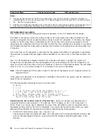
The following diagram defines each part of a location code:
Ux.dd-xx-yy
|
|
|
|
|
|
|
|
|
|
|
yy This code is used for the next component (yy, yy, yy, ...)
|
|
xx This code is used for the next component (Px, Fx, Vx, ...)
|
dd This code is the drawer number for the I/O drawer (2 to 63)
Ux This code normally identifies the rack in which a drawer is installed.
The x will always be zero (0) for this system.
Determining the AIX Location Code of a Physical Slot:
Every slot of every I/O subsystem has a
unique AIX location code assigned to it. For instance, the PCI adapter in slot 1 of I/O subsystem 1 is
29-08. There is no obvious way to determine the value of the
dd
number for the I/O subsystem that is
interpreted by the system as the first I/O subsystem. If you have only the AIX location code, you might
determine the associated I/O subsystem
dd
number by performing the following steps:
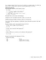
1. On the AIX command line, type
lsdev -Ccadapter |pg
The resulting list gives the logical AIX name of all resources and the corresponding AIX location code.
Look for the appropriate AIX location code, and record the corresponding AIX logical name of the
resource.
34
Eserver
pSeries 630 Model 6C4 and Model 6E4 Service Guide
Summary of Contents for @Server pSeries 630 6C4
Page 1: ...pSeries 630 Model 6C4 and Model 6E4 Service Guide SA38 0604 03 ERserver...
Page 2: ......
Page 3: ...pSeries 630 Model 6C4 and Model 6E4 Service Guide SA38 0604 03 ERserver...
Page 16: ...xiv Eserver pSeries 630 Model 6C4 and Model 6E4 Service Guide...
Page 18: ...xvi Eserver pSeries 630 Model 6C4 and Model 6E4 Service Guide...
Page 382: ...362 Eserver pSeries 630 Model 6C4 and Model 6E4 Service Guide...
Page 440: ...420 Eserver pSeries 630 Model 6C4 and Model 6E4 Service Guide...
Page 538: ...System Parts continued 518 Eserver pSeries 630 Model 6C4 and Model 6E4 Service Guide...
Page 541: ...Chapter 10 Parts Information 521...
Page 562: ...542 Eserver pSeries 630 Model 6C4 and Model 6E4 Service Guide...
Page 568: ...548 Eserver pSeries 630 Model 6C4 and Model 6E4 Service Guide...
Page 576: ...556 Eserver pSeries 630 Model 6C4 and Model 6E4 Service Guide...
Page 580: ...560 Eserver pSeries 630 Model 6C4 and Model 6E4 Service Guide...
Page 616: ...596 Eserver pSeries 630 Model 6C4 and Model 6E4 Service Guide...
Page 646: ...626 Eserver pSeries 630 Model 6C4 and Model 6E4 Service Guide...
Page 649: ......


