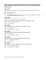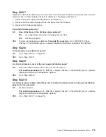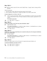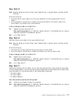
MAP 1520: Power
Notes:
1. This is not a start-of-call MAP. Use this Power MAP only if you have been directed here from another
MAP, an SRN in the
RS/6000
Eserver
pSeries Diagnostic Information for Multiple Bus Systems
, or an
error code.
2. This procedure is used to locate power problems in system units. If a problem is detected, this
procedure helps you isolate the problem to a failing unit.
3. The pSeries 630 Model 6C4 and Model 6E4 can accommodate two power supplies installed with
separate power receptacles on the rear of the power supply. There are three LEDs located on the front
and top of the power supply:
v
AC Good LED (green)
v
DC Good LED (green)
v
Power Supply Fault Indicator LED (amber)
The LEDs indicate the condition of the power supply. Refer to “Component LEDs” on page 544 for
additional information.
4. The condition of two power supplies being present, but only one working, can be determined by the
service processor and a warning level EPOW.
5. Observe the following safety notices during service procedures.
DANGER
An electrical outlet that is not correctly wired could place hazardous voltage on metal parts of
the system or the devices that attach to the system. It is the responsibility of the customer to
ensure that the outlet is correctly wired and grounded to prevent an electrical shock.
Before installing or removing signal cables, ensure that the power cables for the system unit
and all attached devices are unplugged.
When adding or removing any additional devices to or from the system, ensure that the power
cables for those devices are unplugged before the signal cables are connected. If possible,
disconnect all power cables from the existing system before you add a device.
Use one hand, when possible, to connect or disconnect signal cables to prevent a possible
shock from touching two surfaces with different electrical potentials.
During an electrical storm, do not connect cables for display stations, printers, telephones, or
station protectors for communications lines.
D05
CAUTION:
This product is equipped with a three-wire power cable and plug for the user’s safety. Use this
power cable with a properly grounded electrical outlet to avoid electrical shock.
C01
Chapter 3. Maintenance Analysis Procedures (MAPs)
105
Summary of Contents for @Server pSeries 630 6C4
Page 1: ...pSeries 630 Model 6C4 and Model 6E4 Service Guide SA38 0604 03 ERserver...
Page 2: ......
Page 3: ...pSeries 630 Model 6C4 and Model 6E4 Service Guide SA38 0604 03 ERserver...
Page 16: ...xiv Eserver pSeries 630 Model 6C4 and Model 6E4 Service Guide...
Page 18: ...xvi Eserver pSeries 630 Model 6C4 and Model 6E4 Service Guide...
Page 382: ...362 Eserver pSeries 630 Model 6C4 and Model 6E4 Service Guide...
Page 440: ...420 Eserver pSeries 630 Model 6C4 and Model 6E4 Service Guide...
Page 538: ...System Parts continued 518 Eserver pSeries 630 Model 6C4 and Model 6E4 Service Guide...
Page 541: ...Chapter 10 Parts Information 521...
Page 562: ...542 Eserver pSeries 630 Model 6C4 and Model 6E4 Service Guide...
Page 568: ...548 Eserver pSeries 630 Model 6C4 and Model 6E4 Service Guide...
Page 576: ...556 Eserver pSeries 630 Model 6C4 and Model 6E4 Service Guide...
Page 580: ...560 Eserver pSeries 630 Model 6C4 and Model 6E4 Service Guide...
Page 616: ...596 Eserver pSeries 630 Model 6C4 and Model 6E4 Service Guide...
Page 646: ...626 Eserver pSeries 630 Model 6C4 and Model 6E4 Service Guide...
Page 649: ......


