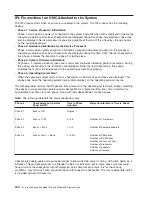
Checkpoint
Description
Action/
Possible Failing FRU
E1DC
Description:
Dynamic console selection.
Action/Possibly Failing FRU
1. If a console is attached, but nothing is displayed on it, go to
″
All display problems
″
in
the Entry MAP.
2. If selection screens can be seen on the terminals and the appropriate key on the
input device is pressed within 60 seconds but there is no response to the keystroke:
a. If selecting the console with a keyboard attached to the system, replace the
keyboard, then replace the CEC backplane, Location: U0.1-P1.
b. If selecting the console with an ASCII terminal, suspect the terminal. Use the
problem determination procedures for the terminal.
Note:
Terminal setting should be:
v
9600 baud
v
no parity
v
8 data bits
v
1 stop bit
E1F0
Start O.B.E.
Go to “MAP 1540: Problem Isolation
Procedures” on page 124.
E1F1
Begin selftest sequence on boot devices.
Go to “MAP 1540: Problem Isolation
Procedures” on page 124.
E1F2
Power-on password prompt
The prompt should be visible on the
firmware console (maybe a virtual terminal
on the HMC).
If a console is attached but nothing is
displayed on it, go to the “Quick Entry
MAP” on page 63 with the symptom
″
All
display problems.
″
E1F3
Privileged-access password prompt
The prompt should be visible on the
firmware console (maybe a virtual terminal
on the HMC).
If a console is attached but nothing is
displayed on it, go to the “Quick Entry
MAP” on page 63 with the symptom
″
All
display problems.
″
E1F4
End self-test sequence on boot devices;
begin SMS.
Go to “MAP 1540: Problem Isolation
Procedures” on page 124.
E1F5
Build boot device list
Go to “MAP 1540: Problem Isolation
Procedures” on page 124.
E1F6
Determine boot device sequence
Go to “MAP 1540: Problem Isolation
Procedures” on page 124.
E1F7
No boot image located
Go to “Boot Problems/Concerns” on
page 204.
E1F8
Building boot device list for SCSI adapters.
(The location of the SCSI adapter being
scanned is also displayed.)
1. If a location code is available, follow the
Repair actions listed for error code
21A0 00XX.
2. If no location code is available, go to
“MAP 1540: Problem Isolation
Procedures” on page 124.
Chapter 4. Checkpoints
173
Summary of Contents for @Server pSeries 630 6C4
Page 1: ...pSeries 630 Model 6C4 and Model 6E4 Service Guide SA38 0604 03 ERserver...
Page 2: ......
Page 3: ...pSeries 630 Model 6C4 and Model 6E4 Service Guide SA38 0604 03 ERserver...
Page 16: ...xiv Eserver pSeries 630 Model 6C4 and Model 6E4 Service Guide...
Page 18: ...xvi Eserver pSeries 630 Model 6C4 and Model 6E4 Service Guide...
Page 382: ...362 Eserver pSeries 630 Model 6C4 and Model 6E4 Service Guide...
Page 440: ...420 Eserver pSeries 630 Model 6C4 and Model 6E4 Service Guide...
Page 538: ...System Parts continued 518 Eserver pSeries 630 Model 6C4 and Model 6E4 Service Guide...
Page 541: ...Chapter 10 Parts Information 521...
Page 562: ...542 Eserver pSeries 630 Model 6C4 and Model 6E4 Service Guide...
Page 568: ...548 Eserver pSeries 630 Model 6C4 and Model 6E4 Service Guide...
Page 576: ...556 Eserver pSeries 630 Model 6C4 and Model 6E4 Service Guide...
Page 580: ...560 Eserver pSeries 630 Model 6C4 and Model 6E4 Service Guide...
Page 616: ...596 Eserver pSeries 630 Model 6C4 and Model 6E4 Service Guide...
Page 646: ...626 Eserver pSeries 630 Model 6C4 and Model 6E4 Service Guide...
Page 649: ......


