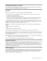
Powering the System on and Off
For procedures to power off and power on the system for various system configurations and operating
systems, see “Stopping and Starting Your System” on page 424.
Console
Note:
This section applies to a system that does not have an HMC attached.
The firmware starts a console-selection sequence at system boot time if any of the following is true:
v
A console has not yet been selected.
v
A previous console-selection sequence timed out.
v
A change in the system configuration affects the console (for example, keyboard installed or removed,
mouse installed or removed, graphics adapter installed/removed or moved to another PCI slot).
The console-selection sequence allows you to select (from the appropriate input device) any one of the
available console devices. If no console is selected within approximately 60 seconds, serial port 1 (S1) is
selected as the console and the selection sequence times out.
Attention:
If an ASCII terminal is attached to serial port 1 (S1), and there is any interaction with this
terminal:
v
After
OK
displays in the operator panel
AND
v
Before the power-on sequence is initiated
the firmware will use this terminal as the console, regardless of the previous console selection.
After a console has been selected, the console-selection sequence is started at boot time only if there is a
change in the system configuration (as previously described), or the contents of the system’s nonvolatile
memory (NVRAM) are lost.
Note:
Moving an ASCII terminal from one serial port to another (from S1 to S2) cannot be detected by the
firmware, so it does not constitute a configuration change.
You can also initiate a system console-selection sequence from the SMS menus.
Power-On Self-Test
After power is turned on and before the operating system is installed, the system does a power-on self-test
(POST). This test performs checks to ensure that the hardware is functioning correctly before the
operating system is installed. During the POST, a POST screen displays, and POST indicators appear on
the firmware console (if one is connected). The next section describes the POST indicators and functions
that can be accessed during the POST.
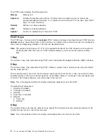
POST Indicators
POST indicators indicate tests that are being performed as the system is preparing to load the operating
system. The POST indicators are words that display on the system console. Each time that the system
starts a different step in the POST, a POST indicator word appears on the console. Each word is an
indicator of the tests that are being performed.
Chapter 1. Reference Information
7
Summary of Contents for @Server pSeries 630 6C4
Page 1: ...pSeries 630 Model 6C4 and Model 6E4 Service Guide SA38 0604 03 ERserver...
Page 2: ......
Page 3: ...pSeries 630 Model 6C4 and Model 6E4 Service Guide SA38 0604 03 ERserver...
Page 16: ...xiv Eserver pSeries 630 Model 6C4 and Model 6E4 Service Guide...
Page 18: ...xvi Eserver pSeries 630 Model 6C4 and Model 6E4 Service Guide...
Page 382: ...362 Eserver pSeries 630 Model 6C4 and Model 6E4 Service Guide...
Page 440: ...420 Eserver pSeries 630 Model 6C4 and Model 6E4 Service Guide...
Page 538: ...System Parts continued 518 Eserver pSeries 630 Model 6C4 and Model 6E4 Service Guide...
Page 541: ...Chapter 10 Parts Information 521...
Page 562: ...542 Eserver pSeries 630 Model 6C4 and Model 6E4 Service Guide...
Page 568: ...548 Eserver pSeries 630 Model 6C4 and Model 6E4 Service Guide...
Page 576: ...556 Eserver pSeries 630 Model 6C4 and Model 6E4 Service Guide...
Page 580: ...560 Eserver pSeries 630 Model 6C4 and Model 6E4 Service Guide...
Page 616: ...596 Eserver pSeries 630 Model 6C4 and Model 6E4 Service Guide...
Page 646: ...626 Eserver pSeries 630 Model 6C4 and Model 6E4 Service Guide...
Page 649: ......


