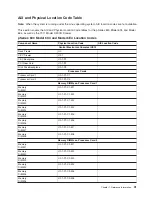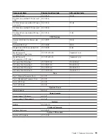
Memory DIMM Location
The memory DIMMs used in the pSeries 630 Model 6C4 and Model 6E4 are located on the processor
card. Your system contains either one or two processor cards, each card with 8 memory DIMM slots.
Associated with each memory DIMM slot is an LED, which is located on the edge of the processor card. A
lit LED indicates a problem with a specific memory DIMM. The following rules must be followed when
removing or installing memory DIMMs:
v
Memory DIMMs must be installed in quads. However, you do not need to install four new DIMMs in a
quad when you have a memory problem. Swap out each DIMM, starting the system after each change,
until the faulty DIMM has been replaced.
Note:
A quad is a group of four memory DIMMs. Each memory DIMM in a quad must be the same type
and size. However, both quads on the same processor card are not required to be the same.
v
The system must have at least four memory DIMMs installed (one quad).
v
The quad slot combinations are 1, 3, 6, and 8 (or 2, 4, 5, and 7).
Note:
1, 3, 6, and 8 (or 2, 4, 5, and 7) combinations are the only slot combinations recognized by the
system.
v
On a two-processor-card system, either processor card can be populated with memory.
Note:
A processor card containing no memory is still functional. (For example, a system containing two
processor cards has all of its memory installed on processor card 1, and no memory installed on
processor card 2. Processor card 2 has no memory-storage capacity, but functions as a
processor card.)
The following are valid memory configurations for one and two processor cards:
Number of Processor Cards
Allowable Memory Configurations
1 Processor Card
1 GB through 16 GB installed in quads of 256 MB DIMMs
to 2 GB DIMMs
2 Processor Cards
1 GB through 32 GB installed in quads of 256 MB DIMMs
to 2 GB DIMMs
Note:
The maximum amount of system memory varies by model.
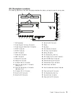
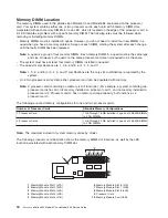
The following processor card illustration shows the memory DIMM slot locations, as well as the LED
location associated with each memory DIMM slot.
1
Memory Module Slot 1 (J2A)
6
Memory Module Slot 6 (J1A)
2
Memory Module Slot 2 (J2B)
7
Memory Module Slot 7 (J0B)
3
Memory Module Slot 3 (J3A)
8
Memory Module Slot 8 (J0A)
4
Memory Module Slot 4 (J3B)
9
Processor Card
5
Memory Module Slot 5 (J1B)
10
Memory Module Fault LEDs
18
Eserver
pSeries 630 Model 6C4 and Model 6E4 Service Guide
Summary of Contents for @Server pSeries 630 6C4
Page 1: ...pSeries 630 Model 6C4 and Model 6E4 Service Guide SA38 0604 03 ERserver...
Page 2: ......
Page 3: ...pSeries 630 Model 6C4 and Model 6E4 Service Guide SA38 0604 03 ERserver...
Page 16: ...xiv Eserver pSeries 630 Model 6C4 and Model 6E4 Service Guide...
Page 18: ...xvi Eserver pSeries 630 Model 6C4 and Model 6E4 Service Guide...
Page 382: ...362 Eserver pSeries 630 Model 6C4 and Model 6E4 Service Guide...
Page 440: ...420 Eserver pSeries 630 Model 6C4 and Model 6E4 Service Guide...
Page 538: ...System Parts continued 518 Eserver pSeries 630 Model 6C4 and Model 6E4 Service Guide...
Page 541: ...Chapter 10 Parts Information 521...
Page 562: ...542 Eserver pSeries 630 Model 6C4 and Model 6E4 Service Guide...
Page 568: ...548 Eserver pSeries 630 Model 6C4 and Model 6E4 Service Guide...
Page 576: ...556 Eserver pSeries 630 Model 6C4 and Model 6E4 Service Guide...
Page 580: ...560 Eserver pSeries 630 Model 6C4 and Model 6E4 Service Guide...
Page 616: ...596 Eserver pSeries 630 Model 6C4 and Model 6E4 Service Guide...
Page 646: ...626 Eserver pSeries 630 Model 6C4 and Model 6E4 Service Guide...
Page 649: ......


