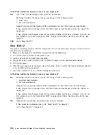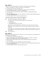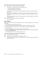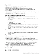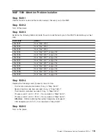
Purpose of this MAP
This MAP is used to locate defective FRUs not found by normal diagnostics. For this procedure,
diagnostics are run on a minimally configured system. If a failure is detected on the minimally configured
system, the remaining FRUs are exchanged one at a time until the failing FRU is identified. If a failure is
not detected, FRUs are added back until the failure occurs. The failure is then isolated to the failing FRU.
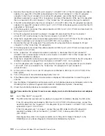
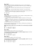
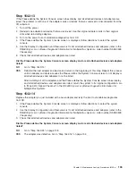
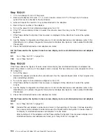
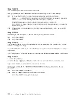
Step 1548-1
1.
Ensure that the diagnostics and the operating system are shut down.
2. Turn on the power.
3. Insert the diagnostic CD-ROM into the CD-ROM drive.
Note:
If you cannot insert the diagnostic CD-ROM, go to “Step 1548-2”.
4. When the
keyboard
indicator is displayed:
v
On an ASCII terminal or hardware management console (HMC), press the number 5 key.
v
On a graphical display, press the number 5 key on the directly attached keyboard.
5. If you are prompted to do so, enter the appropriate password.
Is the
″
Please define the System Console
″
screen displayed?
NO
Go to “Step 1548-2”.
YES
Go to “Step 1548-17” on page 149.
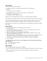
Step 1548-2
1. Turn off the power.
2. If you have not already done so, configure the service processor with the instructions in note 7 on
page 139. Then return here and continue.
3. Exit the service processor menus and remove the power cords.
4. Disconnect all external cables (parallel, serial port 1, serial port 2, serial port 3, keyboard, mouse,
Ethernet, and so on).
5. Remove the service access cover (Model 6E4) or place the drawer (Model 6C4) into the service
position and remove the service access cover.
6. Record the slot numbers of the PCI adapters. Label and record the locations of any cables attached
to the adapters. Disconnect any cables attached to the adapters and remove all the adapters.
7. Disconnect all power and signal cables from the media drives, located in media bay 1 and media bay
2.
8. Remove the media drives as described in “Media Removal” on page 466.
9. Remove the media support shelf by loosening the thumbscrew and grasping the back edge of the
shelf, sliding it back, then lifting it up and out of the system chassis.
Note:
The support leg located on the bottom of the media support shelf is used to deactivate a
microswitch. The microswitch is located on the CEC backplane and when deactivated, cuts off
all power to the CEC backplane. This support shelf must be correctly seated and secured in
position after any new FRU is added to the system.
140
Eserver
pSeries 630 Model 6C4 and Model 6E4 Service Guide
Summary of Contents for @Server pSeries 630 6C4
Page 1: ...pSeries 630 Model 6C4 and Model 6E4 Service Guide SA38 0604 03 ERserver...
Page 2: ......
Page 3: ...pSeries 630 Model 6C4 and Model 6E4 Service Guide SA38 0604 03 ERserver...
Page 16: ...xiv Eserver pSeries 630 Model 6C4 and Model 6E4 Service Guide...
Page 18: ...xvi Eserver pSeries 630 Model 6C4 and Model 6E4 Service Guide...
Page 382: ...362 Eserver pSeries 630 Model 6C4 and Model 6E4 Service Guide...
Page 440: ...420 Eserver pSeries 630 Model 6C4 and Model 6E4 Service Guide...
Page 538: ...System Parts continued 518 Eserver pSeries 630 Model 6C4 and Model 6E4 Service Guide...
Page 541: ...Chapter 10 Parts Information 521...
Page 562: ...542 Eserver pSeries 630 Model 6C4 and Model 6E4 Service Guide...
Page 568: ...548 Eserver pSeries 630 Model 6C4 and Model 6E4 Service Guide...
Page 576: ...556 Eserver pSeries 630 Model 6C4 and Model 6E4 Service Guide...
Page 580: ...560 Eserver pSeries 630 Model 6C4 and Model 6E4 Service Guide...
Page 616: ...596 Eserver pSeries 630 Model 6C4 and Model 6E4 Service Guide...
Page 646: ...626 Eserver pSeries 630 Model 6C4 and Model 6E4 Service Guide...
Page 649: ......

