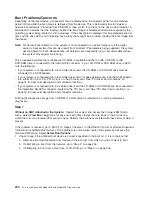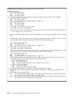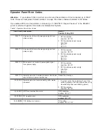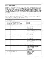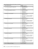
Boot Problems/Concerns
Depending on the boot device, a checkpoint may be displayed on the operator panel for an extended
period of time while the boot image is retrieved from the device. This is particularly true for tape and
network boot attempts. If booting from CD-ROM or tape, watch for activity on the drive’s LED indicator. A
blinking LED indicates that the loading of either the boot image or additional information required by the
operating system being booted is still in progress. If the checkpoint is displayed for an extended period of
time and the drive LED is not indicating any activity, there might be a problem loading the boot image from
the device.
Note:
For network boot attempts, if the system is not connected to an active network or if the target
server is inaccessible (this can also result from incorrect IP parameters being supplied), the system
will still attempt to boot. Because time-out durations are necessarily long to accommodate retries,
the system may appear to be hung.
This procedure assumes that a diagnostic CD-ROM is available and that an IDE CD-ROM or IDE
DVD-RAM drive is connected to the internal IDE connector. If your CD-ROM or DVD-RAM drive is SCSI
note the following:
v
If your system is configured with a four slotted riser card, the CD-ROM or DVD RAM drive must be
connected to a SCSI adapter.
v
If your system is configured with a four slotted riser card, for peek performance load the SCSI adapter
into either PCI-X slot 3 or PCI-X slot 4 on the PCI riser card. See “PCI Riser Card Locations” on
page 16 for riser card description and connector locations.
v
If your system is configured with a six slotted riser card the CD-ROM or DVD-RAM can be connected to
the integratted SE-SCSI connector located on the PCI riser card. See “PCI Riser Card Locations” on
page 16 for riser card description and connector locations.
Booting the diagnostics image from CD-ROM or a NIM server is referred to as running standalone
diagnostics.
Step 1
Without an HMC Attached to the System:
Restart the system and access the firmware SMS main
menu. Select
View Error Log
. Look for any errors with time stamps that are close to the boot during
which the error was received that sent you here. Perform the actions associated with these error code(s) if
present.
If the problem is resolved, go to
″
MAP 410: Repair Checkout
″
in the
RS/6000
Eserver
pSeries Diagnostic
Information for Multiple Bus Systems
. If the problem is not resolved, restart the system and access the
firmware SMS menu. Select
Select Boot Options
.
1. Check to see if the intended boot device is correctly specified in the boot list. If it is in the boot list:
a. Remove all removable media from devices in the boot list from which you do not want to boot.
b. If attempting to boot from the network, go to “Step 2” on page 205.
c. If attempting to boot from a disk drive or CD-ROM, go to “Step 3” on page 206.
204
Eserver
pSeries 630 Model 6C4 and Model 6E4 Service Guide
Summary of Contents for @Server pSeries 630 6C4
Page 1: ...pSeries 630 Model 6C4 and Model 6E4 Service Guide SA38 0604 03 ERserver...
Page 2: ......
Page 3: ...pSeries 630 Model 6C4 and Model 6E4 Service Guide SA38 0604 03 ERserver...
Page 16: ...xiv Eserver pSeries 630 Model 6C4 and Model 6E4 Service Guide...
Page 18: ...xvi Eserver pSeries 630 Model 6C4 and Model 6E4 Service Guide...
Page 382: ...362 Eserver pSeries 630 Model 6C4 and Model 6E4 Service Guide...
Page 440: ...420 Eserver pSeries 630 Model 6C4 and Model 6E4 Service Guide...
Page 538: ...System Parts continued 518 Eserver pSeries 630 Model 6C4 and Model 6E4 Service Guide...
Page 541: ...Chapter 10 Parts Information 521...
Page 562: ...542 Eserver pSeries 630 Model 6C4 and Model 6E4 Service Guide...
Page 568: ...548 Eserver pSeries 630 Model 6C4 and Model 6E4 Service Guide...
Page 576: ...556 Eserver pSeries 630 Model 6C4 and Model 6E4 Service Guide...
Page 580: ...560 Eserver pSeries 630 Model 6C4 and Model 6E4 Service Guide...
Page 616: ...596 Eserver pSeries 630 Model 6C4 and Model 6E4 Service Guide...
Page 646: ...626 Eserver pSeries 630 Model 6C4 and Model 6E4 Service Guide...
Page 649: ......


