Operator Panel
v
32-character LED diagnostics display
v
LEDs for power on, attention, SCSI activity, and LAN activity
v
Buttons for power on, system reset, and service processor reset switch:
System Reset Button
Dumps AIX (if dump is enabled) and reboots
Service Processor Reset Switch
Resets the service processor (into standby mode). The service processor reset switch is the
pinhole located on the operator panel above the system reset button.
Input/Output Ports
v
One 25-pin parallel port (The parallel port is not accessible when in partitioned mode.)
v
Keyboard
v
Mouse
v
Two Ultra3 SCSI (one external Ultra3 SCSI (with VHDCI 4 mini 68-pin port), and one internal Ultra3
SCSI disk drive backplane). VHDCI may require a mini 68-pin connector or FC 2118 mini 68-pin to
68-pin 0.3 meter cable as an additional feature.
v
Integrated Drive Electronics (IDE)
v
Two System Power Control Network (SPCN) Connectors
v
Two RIO Connectors
v
Two 10/100 Ethernet (IEEE 802.3 compliant)
v
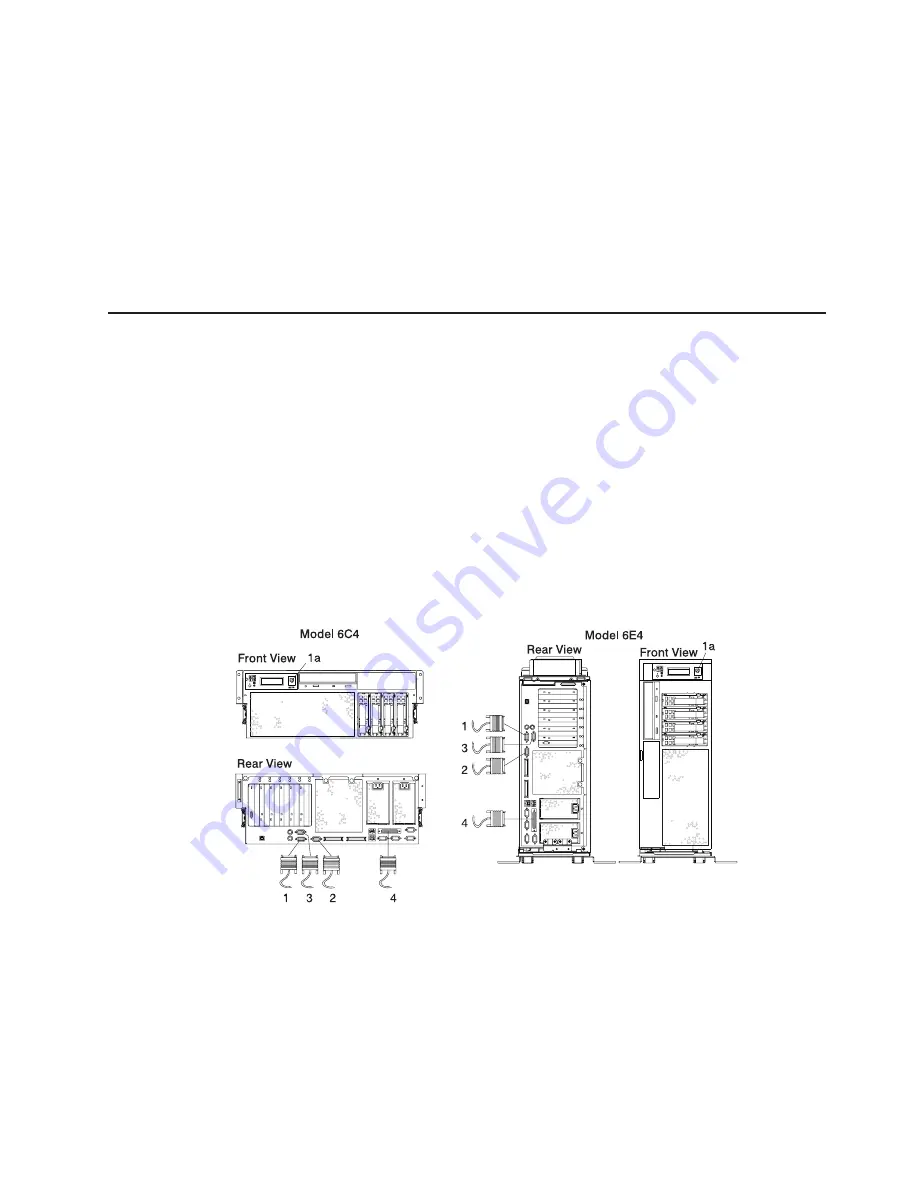
Three serial. Serial port 1 (S1) has two physical connectors, one RJ-48 connector located in front on the
operator panel, and a 9-pin D-shell connector located on the rear of the chassis. The use of the front
port disables the rear S1 port.
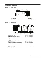
1
Serial Port 1 Connector
3
Serial Port 3 Connector
1a
Serial Port 1 Front Connector (RJ-48)
4
Parallel Connector
2
Serial Port 2 Connector
Chapter 1. Reference Information
5
Summary of Contents for @Server pSeries 630 6C4
Page 1: ...pSeries 630 Model 6C4 and Model 6E4 Service Guide SA38 0604 03 ERserver...
Page 2: ......
Page 3: ...pSeries 630 Model 6C4 and Model 6E4 Service Guide SA38 0604 03 ERserver...
Page 16: ...xiv Eserver pSeries 630 Model 6C4 and Model 6E4 Service Guide...
Page 18: ...xvi Eserver pSeries 630 Model 6C4 and Model 6E4 Service Guide...
Page 382: ...362 Eserver pSeries 630 Model 6C4 and Model 6E4 Service Guide...
Page 440: ...420 Eserver pSeries 630 Model 6C4 and Model 6E4 Service Guide...
Page 538: ...System Parts continued 518 Eserver pSeries 630 Model 6C4 and Model 6E4 Service Guide...
Page 541: ...Chapter 10 Parts Information 521...
Page 562: ...542 Eserver pSeries 630 Model 6C4 and Model 6E4 Service Guide...
Page 568: ...548 Eserver pSeries 630 Model 6C4 and Model 6E4 Service Guide...
Page 576: ...556 Eserver pSeries 630 Model 6C4 and Model 6E4 Service Guide...
Page 580: ...560 Eserver pSeries 630 Model 6C4 and Model 6E4 Service Guide...
Page 616: ...596 Eserver pSeries 630 Model 6C4 and Model 6E4 Service Guide...
Page 646: ...626 Eserver pSeries 630 Model 6C4 and Model 6E4 Service Guide...
Page 649: ......


