


Chapter 9
Page no. 1690
JC-CAL-A-031.fm
GE Healthcare
Senographe DS
Revision 1
Service Information and Procedures Class A 2385072-16-8EN
Job Card CAL A031 - Lift Calibration
6-2-2
Lower Limit Adjustment (Lift Potentiometer Lower Reference Voltage at 0 mm)
Use the following steps to set the lower lift travel limit (which corresponds to the Lift Potentiometer Lower
Reference Voltage):
1. Launch the Service Desktop (see
) then click the
Cali-
bration
button
.
2. From the
Calibration Home Page
that appears, click the
Positionner
button.
3. From the
Calibration : Positioner Summary
page
that appears, click the
Lift
button
.
4. From the
Lift Position and Upper Limit Calibration
page that appears, follow the on-screen instruc-
tions: set the arm rotation position to 0° and remove the Bucky.Then press the
Start
button to start
the calibration process.
The Gantry LCD updates with the following message:
Adjust lower limit. Lower arm until you reach min usable height defined in JC ELE A010. Then press
the FOV button.
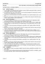
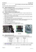
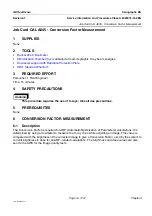
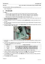
5. Measure the height of the flat surface of the detector (A) with respect to the top of the gantry base
plate (B), as shown.
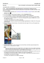
6. Use the control buttons on the Tube Head to move the lift down until the measured height at the
detector is 670 ±2 mm (26.4 ±0.1 inches).
Note:
If you move the detector below the height of 670 ±2 mm height and too close to 660 mm the lower
optical fork will be obstructed and force the Senographe system to halt. If you invoke a halt you will
have to manually move the lift shaft to raise the detector and start again.
7. When the measured height at the detector is 670 ±2 mm (26.4 ±0.1 inches), press the FOV size but-
ton (behind the Tube Head) to signal completion of the lower limit adjustment.
The voltage of the Lift Potentiometer is sent to the firmware of the Lift Board and stored as the Lift
Potentiometer Lower Reference Voltage.
The Gantry LCD updates with the following message:
A
B


