GE Healthcare
Senographe DS
Revision 1
Service Information and Procedures Class A 2385072-16-8EN
Job Card D/R A409 - Relay Board 200-PL4
Page no. 1593
Chapter 9
JC-DR-A-409.fm
board.
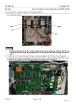
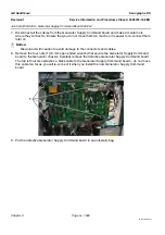
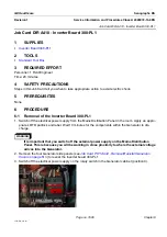
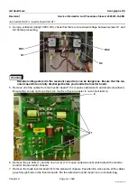
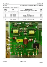
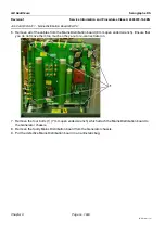
7. Carefully disconnect the data cable (2) from the Generator Relay board. Ensure that you do not move
it too much so it is easier to re-connect it later on.
! Notice:
Disconnect with caution to avoid damage to the connectors and cables.
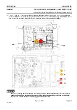
8. Remove the four screws (3) that secure the Generator Relay board (4 mm allen wrench) to the Gen-
erator chassis, and carefully remove the defective Generator Relay board.
9. Put the defective Generator Relay board in an anti-static bag.
6-2
Installation of the Generator Relay Board 200-PL4
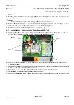
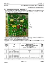
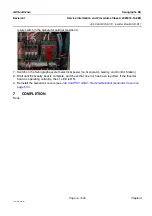
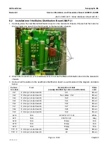
1. Carefully place the new Generator Relay board on the Generator chassis. Ensure that the holes for
the four allen screws line up with the four threads on the Generator chassis.
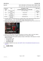
2. Attach the four allen screws (1) (4 mm allen wrench) to secure the Generator Relay board to the
Generator chassis.
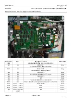
3. Carefully re-connect the data cable (2) to the Generator Relay board. The red line of the ribbon cable
must be on the right-hand side of the connector.
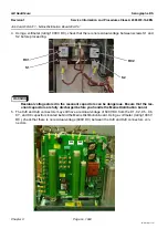
4. Reconnect the lamp and door cables (3) exactly how they were connected before.
5. Re-establish the external power supply to the room lamps.
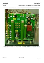
6. Switch on the electrical power supply, both from the Mains Distribution Panel in the room and on the
1
3
2
1


