GE Healthcare
Senographe DS
Revision 1
Service Information and Procedures Class A 2385072-16-8EN
Job Card D/R A191 - PDU Board
Page no. 1141
Chapter 9
JC-DR-A-191.fm
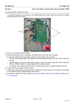
12. Switch on the Gantry electrical power (from the X-ray Console) and check that the Ganrty powers up.
If the Gantry does not power up check that the JP22 jumper is not closed on the bottom two pins.
13. If the Gantry powers up, wait until the Gantry boot is complete, and check that no error has been
reported.
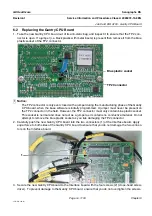
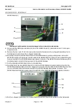
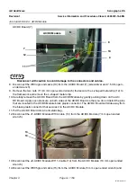
If the PDU board is operating correctly, the LED states are as follows:
•
all the green LEDs below and to the left of connector J3 (i.e. DS15, DS16, DS17, DS18, DS19,
DS20, DS21, and DS22) are ON
•
all of the yellow LEDs above and to the left of connector J3 (i.e. DS9, DS10, DS11, DS12, DS13)
and the red LED (i.e. DS14) are OFF
•
the red LED approximately in the middle of the PDU board (i.e. DS26) is OFF
•
the yellow LED approximately in the middle of the PDU board (i.e. DS25) is blinking and repre-
senting the watchdog heartbeat of the microcontroller on the PDU board
•
the green LEDs above and to the right of connector J2 (i.e DS1 and DS2) are ON
•
the four red LEDs towards the top left of the PDU board (i.e. DS5, DS6, DS7, and DS8) spell the
word
dEF
. If only the third LED from the left shows a 0 and the other LEDs are not lit the PDU
board is still in programming mode and you must ensure that the PRGM jumper is open.
•
the green LED at the bottom, middle part of the PDU board (i.e. DS26) is ON
14. Switch off the Gantry electrical power (form the X-ray Console) and check that the Gantry powers
down. If the Gantry does not power down check that the JP22 jumper is not closed on the top two
pins.
15. Switch off the Senographe electrical power.
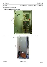
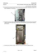
16. Lift the top metal panel up to release it from the left side of the framework. Put it back over the frame-
work to hide the newly installed the newly installed PDU board.
17. Reinstall the left column cover; refer to


