


Chapter 9
Page no. 1508
JC-DR-A-321_DS.fm
GE Healthcare
Senographe DS
Revision 1
Service Information and Procedures Class A 2385072-16-8EN
Job Card D/R A321 - IDC Computer
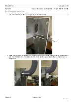
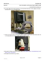
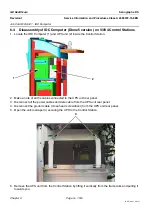
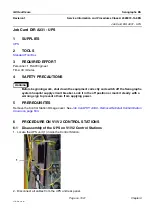
7. .Disconnect the allen screw and bolt (4) connecting the UPS base plate to the L-shaped bracket
(2.5 mm allen wrench).
8. Disconnect the four allen screws and bolts (5) connecting the UPS base plate to the Control Station
framework (5 mm allen wrench and 10 mm open ended wrench).
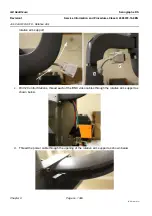
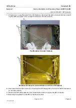
9. Remove the UPS base plate from the Control Station frame to expose the IDC Computer.
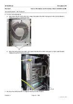
10. Disconnect all cables from the IDC Computer rear panel.
Note:
Note locations of disconnected IDC cables.
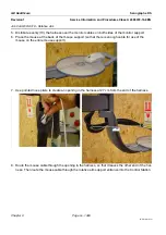
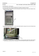
11. Disconnect Ground cable (screwdriver) from the IDC Computer rear panel.
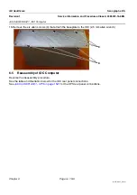
12. Disconnect the fiber optic cables from the IDC Computer rear panel.
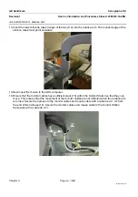
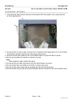
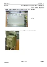
13. Disconnect the power cables and ground cable from the UPS unit rear panel.
14. Disconnect the front two allen (6) screws that attach the IDC Computer to the Control Station frame-
4
5


