


Chapter 9
Page no. 1074
JC-TSG-A-020.fm
GE Healthcare
Senographe DS
Revision 1
Service Information and Procedures Class A 2385072-16-8EN
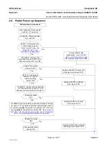
Job Card TSG A020 - Generator Power-Up Sequence Flow Charts
2-5
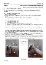
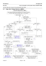
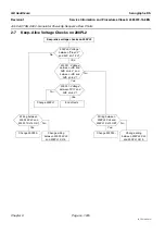
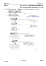
Keep–Alive Voltage Checks on 200PL1
Check that the Generator mains supply switch S1 is closed ("1" position)
and that no attempt has been made to power on the Generator.
Keep–alive voltage checks on 200PL1
200PL1 DE9 lit?
Yes
No
200PL1: voltage
between PT15 and
PT12 at 8 V?
Yes
No
200PL1 DE3 Faulty.
200PL1 DE8 lit?
No
Yes
200PL1 DE8 lit?
No
200PL1: voltage
between PT12 and
PT14 at – 8 V?
Yes
No
200PL1 F3 OK?
Yes
No
Change 200PL1 F3.
Yes
200PL1 DE8 Faulty.
200PL1 F3 OK?
Yes
No
Change 200PL1 F3.
200PL1: Disconnect XJ15
No
Yes
200PL1 DE8
and DE9 lit?
200PL1:Re-connect XJ15
200PL1: Disconnect XJ14
No
Yes
200PL1 DE8
and DE9 lit?
Cable bundle between
(including connectors)
200PL1 XJ15 and
200PL2 XJ4 OK?
Yes
Yes
Change 200PL2.
Replace the cable bundle between
200PL1 connector XJ15 and
200PL2 connector XJ4.
No
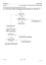
200PL1 DE2 lit?
200PL1 DE3 lit?
See
200PL1: voltage
between PT1 and
PT2 at 12 V?
Yes
200PL1 DE2 Faulty.
Yes
No
No
200PL1: voltage
between PT2 and
PT3 at 12 V?
200PL1 DE2 Faulty.
Yes
No
No
200PL1 F1 OK?
Yes
No
Change 200PL1 F3.
200PL1: Disconnect XJ14
No
Yes
200PL1 DE3
and DE2 lit?
200PL1:Re-connect XJ14
200PL2: Disconnect XJ2
No
Yes
200PL1 DE3
and DE2 lit?
See
See
Cable bundle between
(including connectors)
200PL1 XJ14 and
200PL2 XJ2 OK?
Yes
Change 200PL2.
Replace the cable bundle between
200PL1 connector XJ14 and
200PL2 connector XJ2.
No


