


Chapter 7
Page no. 782
JC-ELE-A-060.fm
GE Healthcare
Senographe DS
Revision 1
Service Information and Procedures Class A 2385072-16-8EN
Job Card ELE A060 - Image Receptor Installation
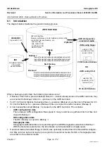
6
PROCEDURE
Note:
The Senographe system is shipped and delivered with the Image Receptor not installed.
The system is assembled and calibrated as usual on the manufacturing line. The Image Receptor
is then removed from the system and packed in a separate box with additional thermal protection.
6-1
Before Installation of the Digital Detector
1. Turn Gantry power OFF.
2. Remove the Compression and Arm covers (refer to
Job Card PHY A044 - Remove/Reinstall Gantry
3. Turn Gantry power ON.
4. Set the Arm to an intermediate height.
5. Rotate the arm to between a working position of –45° to + 45°.
! Notice:
Never rotate the arm outside of the range –45° to + 45° when installing the Digital Detector. If the
coolant pipes are not secured properly and if this arm angle range is not respected, there is a risk
of coolant entering the inner workings of the Digital Detector.
6. Turn Gantry power off.
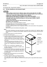
7. Switch off the Conditioner (the Generator covers are currently uninstalled at this stage, so you do not
have to remove them to access the Conditioner).
6-2
Installation of Digital Detector
CAUTION
Two people are required for installation of the Digital
Detector. Never allow the mass of the detector to fall
onto its alignment pins before the securing screws have
been correctly fitted.
1. Before starting to fit the Detector, prepare the securing screws.
Apply a small amount of locking compound Loctite 222 to the
threads of each screw.
2. While one person holds the detector against its alignment pins
on the interface plate, the other fits and tightens the two upper
securing screws (1) to hold it in position (5 mm allen wrench,
torque 8.5 N.m).
3. Fit and tighten the two lower securing screws (5 mm allen
wrench, torque 8.5 N.m).
4. Fit and tighten the screw securing the ground cable terminal
(4 mm allen wrench).
1


