GE Healthcare
Senographe DS
Revision 1
Service Information and Procedures Class A 2385072-16-8EN
Job Card PHY A016 - AC Connection
Page no. 471
Chapter 6
JC-PHY-A-016.fm
6-3
Voltage Selection - Generator
6-3-1
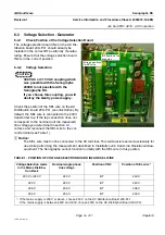
Check Position of the Voltage Selection Board
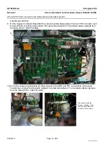
The voltage selection board IN2 on the AC Dis-
tribution board 200–PL1 should already be
installed in the correct BT position by manufac-
turing. Ensure that the voltage selection board
IN2 is in the correct position.
6-3-2
Voltage Selection
CAUTION
380 VAC or 415 VAC coupling which
was possible with the Senographe
2000D is not possible with the
Senographe DS.
If you choose this coupling, you will
destroy the Gantry power supply.
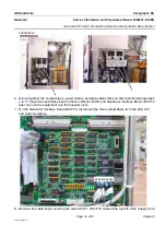
Check the position of the SEL wire on the AC
Distribution board 200–PL1 (see illustration). By
default, the SEL wire is connected to the 240 V
transformer tap. If the tap connection does not
correspond to the nominal (
not the measured)
line voltage you determined in section
remove and reconnect the SEL wire to the cor-
rect terminal (see Table 1).
! Notice:
The SEL wire must not be connected to the 0V terminal. This terminal is reserved exclusively for
use while performing the measurement described in Installation Job Card
Line Resistance Mea-
surement
. The Senographe cannot function normally with the SEL wire in this position.
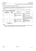
TABLE 1 - POSITION OF VOLTAGE SELECTION BOARD IN2 AND SEL WIRE
Voltage Selection made
in the Mains Distribu-
tion Rack
Nominal single phase
line voltage
Position of IN2
Position of SEL wire *
230 V or 240 V
240 V
BT
240 V
220 V
220 V
BT
220 V
208 V
208 V
BT
208 V
200 V
200 V
BT
200 V
* - If the mains supply is 230 V or above, choose 240 V on the AC Distribution Board 200-PL1.
If the mains supply is between 220V and 230V, choose 220V on the AC Distribution Board 200-PL1.
Voltage positions
for SEL wire
IN2 board on left
hand side


