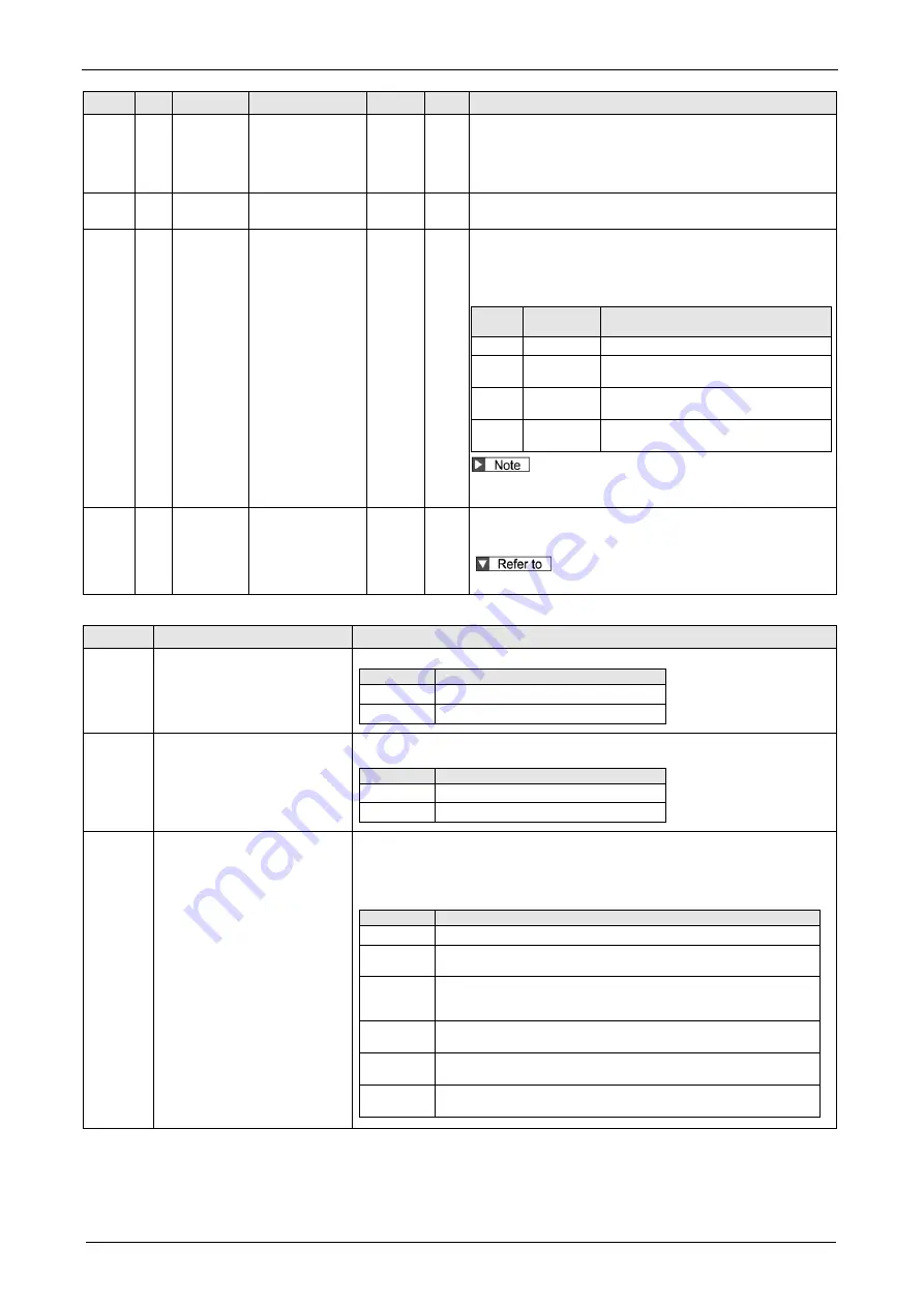
Auto Tuning Functions
5-4
Class No. Attribute
Title
Range Unit Function
0
03
B
Real-time
auto-tuning
machine stiffness
setup
0 to 31
-
You can set up the response while the real-time auto-gain tuning
is valid. Higher the setup value, higher the velocity response and
servo stiffness will be obtained. However, when increasing the
value, check the resulting operation to avoid oscillation or
vibration.
6
10
B
Function expansion
setup
-32768
to 32767
-
The automatic adjustment of load change inhibit function is
enabled with bit14=1.
6
31
B
Real time auto
tuning estimation
speed
0 to 3
Set up the load characteristics estimation speed with the
Real-time auto tuning being valid. A higher setup value assures
faster response to a change in load characteristics but increases
variations in disturbance estimation. Result of estimation is saved
to EEPROM every 30 minutes.
Setup
value
Mode
Description
0
No change
Stop estimation of load characteristics.
1
Almost
constant
Response to changes in load characteristics
in every minute.
2
Slower
change
Response to changes in load characteristics
in every second.
3 *
Faster
change
Obtain best suitable estimation in response to
changes in load characteristics.
If the automatic oscillation detection is enabled by the support
software, the setup value 3 is used.
6
32
B
Real time auto
tuning custom
setup
-32768
to 32767
-
When the operation mode of real time auto tuning is set to the
customize (Pr 0.02 = 6), set the automatic adjusting function as
shown below.
Real time auto tuning custom setup
Real time auto tuning custom setup
Bit
Content
Description
1 to 0
Load characteristics estimation
(Note 1)(Note 2)
Enable/disable the load characteristics estimation function.
Setup value Description
0
Disable
1
Enable
3 to 2
Inertia ratio update
(Note 3)
Set up update to be made based on result of the load characteristics estimation of Pr
0.04 “Inertia ratio”.
Setup value Description
0
Use current setup
1
Update by the estimated value.
6 to 4
Torque compensation
(Note 4)
Set up the update to be made according to the results of load characteristics
estimation:
Pr 6.07 "Torque command additional value"
Pr 6.08 "positive direction torque compensation value"
Pr 6.09 "negative direction torque compensation value".
Setup value Description
0
Use current setup
1
Disable torque compensation.
Clear the parameters shown above to 0.
2
Vertical axis mode
Update Pr 6.07.
Zero clear Pr 6.08 and Pr 6.09
3
Friction compensation (low)
Update Pr 6.07. Set low compensation to Pr 6.08 and Pr 6.09.
4
Friction compensation (middle)
Set middle compensation to Pr 6.08and Pr.6.09
5
Friction compensation (high)
Set high compensation to Pr 6.08 and Pr 6.09.
(To be continued)
Summary of Contents for MINAS A6 Series
Page 10: ...Table of contents x Blank page...
Page 11: ...1 Introduction...
Page 26: ...Introduction 1 16 Blank page...
Page 27: ...2 Interface Specifications...
Page 46: ...Interface Specifications 2 20 Blank page...
Page 47: ...3 Front Panel Specifications...
Page 57: ...4 Basic Functions...
Page 85: ...5 Auto Tuning Functions...
Page 151: ...6 Application Functions...
Page 185: ...7 Protective Functions...
Page 224: ...Protective Functions 7 40 Blank page...
Page 225: ...8 Advanced Safety Functions...
Page 230: ...Advanced Safety Functions 8 6 When test pulse is used Duplex safety input Safety input...
Page 245: ...9 List of Parameters...
Page 281: ...10 Timing Chart...
Page 290: ...Timing Chart 10 10 Blank page...
Page 291: ...11 Power Supply Module...


