4.5Full-closed control
4-21
(Note 2) For the direction of external scale connection, make sure to connect so that the scale counting direction becomes as the count-up
when the motor axis is rotated to the CCW direction, and as the count-down when the motor shaft is rotated to the CW direction.
If the above mentioned directions are not possible depending on the installation conditions and others, the scale counting
direction can be inverted using Pr3.26 "Reversal of direction of external scale".
The installation direction can be checked PANATERM for Multi(USB communication, EoE communication),by checking the
counting directions of external scale feedback pulse summation and encoder feedback pulse summation. When they are in
agreement, the connection is established correctly. If they do not match, invert the set value of Pr3.26 "Reversal of direction of
external scale" (0 to 1 or 1 to 0).
(Note 3) Supporting velocity means the feedback speed [pulse/s] of external scale that can be processed in the driver side.For the
information on available range in the scale side, please check in the specification sheet for the scale.For example, when using a
serial communication type external scale having the resolution of 1 nm, the maximum speed is 4 m/s. Even with the full-closed
control, the overspeed protection occurs if the motor axis rotation speed exceeds the maximum speed.
(Note 4) Others, please contact the Company for supporting external scales.
4.5.2 Setting of external scale division ratio
This section describes the setting of division ratio with encoder resolution and external scale resolution.
Relevant parameters
Class No. Attribute
Title
Range Unit Function
3
24
R
Numerator of
external scale
divison
0 to 2
23
-
Sets the numerator of external scale division setting.
When the set value = 0, the operation is performed with the
encoder resolution used as the division numerator.
3
25
R
Denominator of
external Scale
divison
1 to 2
23
-
Sets the denominator of external scale division setting.
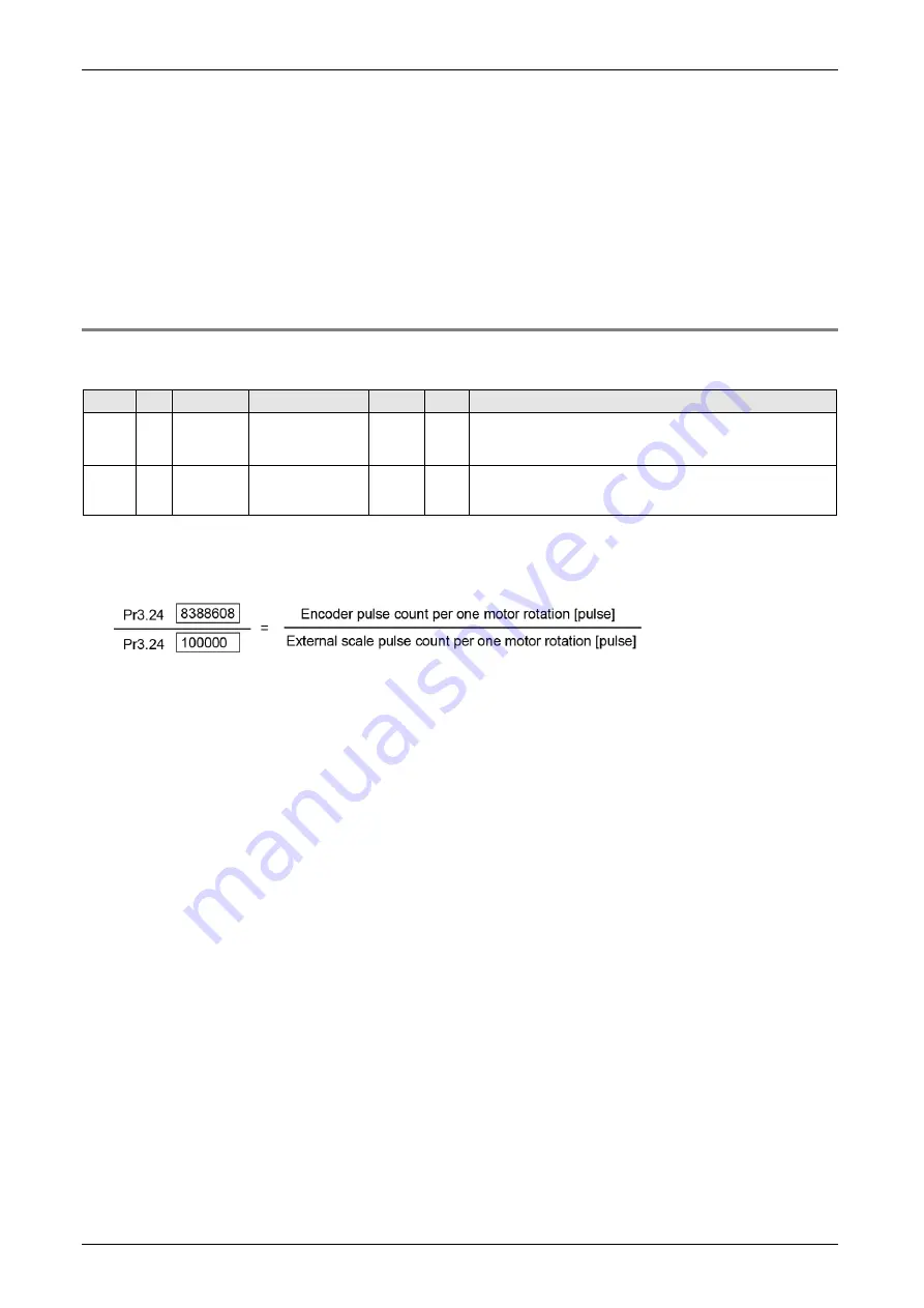
Check the encoder pulse count per one motor rotation and the external scale pulse count per one motor
rotation, then set the numerator of external scale division (Pr3.24) and denominator of external scale division
(Pr3.25) so that the equation below becomes true.
Example) With 10mm ball screw pitch, 0.1μm/pulse scale, 23-bit (8,388,608pulse/r) encoder resolution
If the ratio is incorrect, the difference increases between the position calculated from encoder pulse and the
position calculated from external scale pulse, and the hybrid deviation excess error protection occurs
especially when the movement distance is long.
When Pr3.24 is set to 0, the encoder resolution is automatically set as the numerator.
Summary of Contents for MINAS A6 Series
Page 10: ...Table of contents x Blank page...
Page 11: ...1 Introduction...
Page 26: ...Introduction 1 16 Blank page...
Page 27: ...2 Interface Specifications...
Page 46: ...Interface Specifications 2 20 Blank page...
Page 47: ...3 Front Panel Specifications...
Page 57: ...4 Basic Functions...
Page 85: ...5 Auto Tuning Functions...
Page 151: ...6 Application Functions...
Page 185: ...7 Protective Functions...
Page 224: ...Protective Functions 7 40 Blank page...
Page 225: ...8 Advanced Safety Functions...
Page 230: ...Advanced Safety Functions 8 6 When test pulse is used Duplex safety input Safety input...
Page 245: ...9 List of Parameters...
Page 281: ...10 Timing Chart...
Page 290: ...Timing Chart 10 10 Blank page...
Page 291: ...11 Power Supply Module...


