Basic Functions
4-26
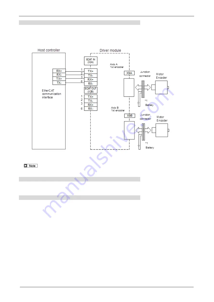
Structure of absolute system
Absolute system configuration using EtherCAT communication interface
(Example: with driver module 2-axes connection)
In the EtherCAT communication response (driver to host controller), the absolute data is transferred to
the host controller as the current position data.
*1 When connecting the battery, connect it to the junction connector on either the connector X9A/X9B side or the encoder side. Do not
connect to both.
During replacing the battery, the control power input must be held ON. If not so, the absolute data will be lost.
Installing battery for absolute data
Refer to "REFERENCE SPECIFICATIONS Driver module section (SX-DSV03454)".
Clearing of absolute data
Multi-turn data of the absolute data is hold by the battery.
Therefore, when you start up the machine for the first time, it is required to make the multi-turn data to
0 by encoder clearing at the home position after installing the battery.
Clearing operation of absolute encoder is made through PANATERM for Multi(USB communication,
EoE communication) or EtherCAT communication. After clearing the absolute data, turn OFF and ON the
control power.
For information about clearing via PANATERM for Multi(USB communication, EoE communication),
refer to the operating manual of PANATERM for Multi.
For information about clearing via EtherCAT communication, refer to "TECHNICAL REFERENCE
EtherCAT Communication Specification (SX-DSV03456)".
Summary of Contents for MINAS A6 Series
Page 10: ...Table of contents x Blank page...
Page 11: ...1 Introduction...
Page 26: ...Introduction 1 16 Blank page...
Page 27: ...2 Interface Specifications...
Page 46: ...Interface Specifications 2 20 Blank page...
Page 47: ...3 Front Panel Specifications...
Page 57: ...4 Basic Functions...
Page 85: ...5 Auto Tuning Functions...
Page 151: ...6 Application Functions...
Page 185: ...7 Protective Functions...
Page 224: ...Protective Functions 7 40 Blank page...
Page 225: ...8 Advanced Safety Functions...
Page 230: ...Advanced Safety Functions 8 6 When test pulse is used Duplex safety input Safety input...
Page 245: ...9 List of Parameters...
Page 281: ...10 Timing Chart...
Page 290: ...Timing Chart 10 10 Blank page...
Page 291: ...11 Power Supply Module...


