11.2Interface specifications
11-3
11.2 Interface specifications
11.2.1 Connector for Inter-module communication
Connect the inter-module communication cable that exchanges information with the driver module.
Name of signal
Signal
Connector pin No. Content
Data (+)
DATA+
1
This is the data signal (+).
Data (-)
DATA-
2
This is the data signal (-).
Manufacturer use
-
3
Manufacturer use
-
4
Emergency
EMG
5
This is the power supply module alarm output signal.
Ground
GND
6
This is the signal ground.
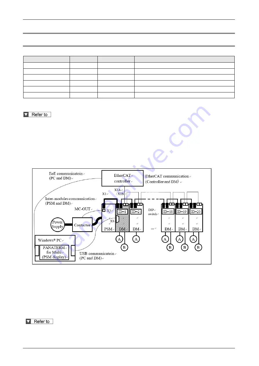
There is one inter-module communication connector for the power supply module (X1) and two for each
driver module (X1A, X1B), connect the communication cable as shown below.
For details, refer to "REFERENCE SPECIFICATIONS Power supply module section (SX-DSV03452)"
and "REFERENCE SPECIFICATIONS Driver module section (SX-DSV03454)".
Use the DIP switch on the front panel of each driver module to set the inter-module communication
node address (ID) with a different number between 1 and 20 for the driver modules connected to the
same power supply module. For details, refer to "3.2 Node address setup in Inter-module communication"
in this document.
Set the inter-module communication node address (ID) to 1 for one of the driver modules connected to
the same power supply module. Otherwise, the power supply module will detect PSM Err.26 “PSM
module communication ID error protection”.
The following functions are added to the driver module whose inter-module communication node
address (ID) is 1.
PSM parameter setting, monitoring, confirmation of alarm information
Using the setup support software PANATERM for Multi that runs on a Windows® PC, it is possible to check
the parameters, monitor, and alarm information of the power supply module via USB communication of the
driver module via inter-module communication.
If there is an abnormality in the inter-module communication due to disconnection of the inter-module
communication cable, it is not possible to communicate with PANATERM for Multi. Turn it off and re-turn it
on.
For details, refer to the operation manual of the setup support software PANATERM for Multi.
* Windows® is a registered trademark of Microsoft Corporation in the United States and other countries.
Summary of Contents for MINAS A6 Series
Page 10: ...Table of contents x Blank page...
Page 11: ...1 Introduction...
Page 26: ...Introduction 1 16 Blank page...
Page 27: ...2 Interface Specifications...
Page 46: ...Interface Specifications 2 20 Blank page...
Page 47: ...3 Front Panel Specifications...
Page 57: ...4 Basic Functions...
Page 85: ...5 Auto Tuning Functions...
Page 151: ...6 Application Functions...
Page 185: ...7 Protective Functions...
Page 224: ...Protective Functions 7 40 Blank page...
Page 225: ...8 Advanced Safety Functions...
Page 230: ...Advanced Safety Functions 8 6 When test pulse is used Duplex safety input Safety input...
Page 245: ...9 List of Parameters...
Page 281: ...10 Timing Chart...
Page 290: ...Timing Chart 10 10 Blank page...
Page 291: ...11 Power Supply Module...


