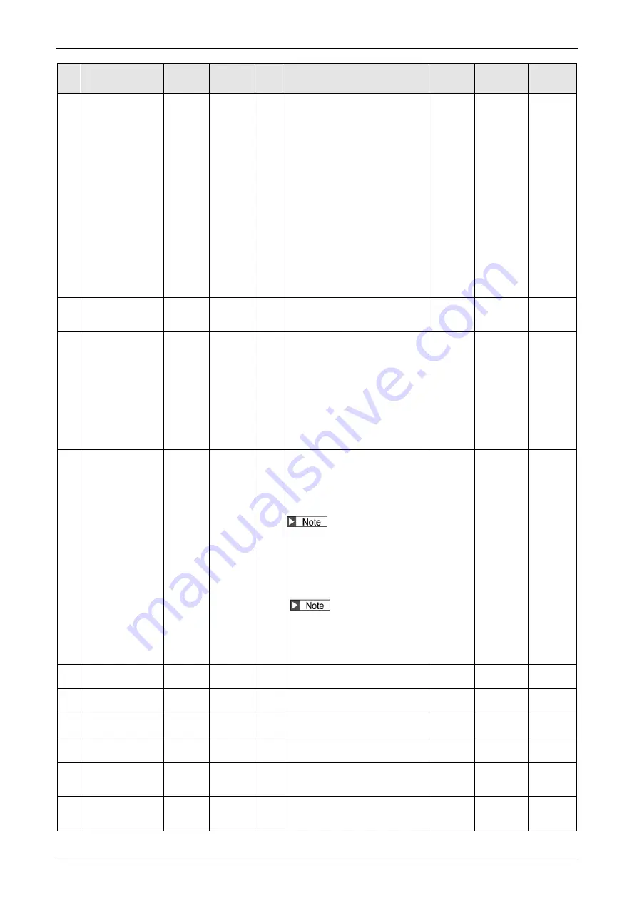
9.1List of parameters
9-21
No. Title
Unit
Range
Size
[byte]
Function/Contents
Attribute
Related
control
mode
Reference
11
Current response
setup
%
10 to 300 2
Adjust the current response with the
level set at shipment as 100%.
In principle, specify 100 for this
setting and adjust the
position/velocity gain. While the
response can be improved by
setting this value to a value larger
than 100 when it is wished that the
servo response is further improved,
it may also result in a tendency for
vibration and noise generation.
Adjust it to an appropriate value
depending on the operating
conditions of the applied device in a
similar fashion to the adjustment of
position/velocity gain. The maximum
value which can be set varies by the
type of motor connected, and the
maximum value is limited to 100%
for some of the motors.
B
all
-
14
Emergency stop
time at alarm
ms
0 to 1000 2
Set up the time allowed to complete
emergency stop in an alarm
condition.
B
All
15
2nd over-speed
level setup
r/min
0 to
20000
2
Set up the detection level of Err.26.1
2nd over-speed protection.
If the motor speed exceeds this
setup value, Err26.1 “2nd
over-
speed protection” occurs.
When the setting value is 0, the
over-speed level becomes the
over-speed protection level.The
internal value is limited to the
over-speed level of applicable
motor.(Note 1)
B
All
18
Power-up wait time
0.1 s
0 to 100
2
Set up the standard initialization
time approx. 1.5 s +
α (setting value
x 0.1s) after power-up.
For example, in the case of the
preset value 10, it is set to
1.5s+(10×0.1 s) = approx. 2.5s.
If the period until LINK
establishment is too long, it may be
possible to improve this
phenomenon by setting different
values in the Pr6.18 for adjacent
driver modules (such as 0.0 s and
0.1 s).
If error F8301/F8302 is detected
from the safety part after turning on
the power, the phenomenon may be
improved by reducing the value of
Pr6.18.
R
S
All
19
For manufacturer’s
use
-
-
2
Permanently set at 0.
-
-
-
20
For manufacturer’s
use
-
-
2
Permanently set at 0.
-
-
-
21
For manufacturer’s
use
-
-
4
Permanently set at 0.
-
-
-
22
For manufacturer’s
use
-
-
2
Permanently set at 0.
-
-
-
23
Load change
compensation gain
%
-100 to
100
2
Set the compensation gain for a load
change.
B
Position,
Velocity,
Full-closed
24
Load change
compensation filter
0.01 ms
10 to
2500
2
Set the compensation gain for a load
change.
B
Position,
Velocity,
Full-closed
(Note 1) Except some motors
(To be continued)
Summary of Contents for MINAS A6 Series
Page 10: ...Table of contents x Blank page...
Page 11: ...1 Introduction...
Page 26: ...Introduction 1 16 Blank page...
Page 27: ...2 Interface Specifications...
Page 46: ...Interface Specifications 2 20 Blank page...
Page 47: ...3 Front Panel Specifications...
Page 57: ...4 Basic Functions...
Page 85: ...5 Auto Tuning Functions...
Page 151: ...6 Application Functions...
Page 185: ...7 Protective Functions...
Page 224: ...Protective Functions 7 40 Blank page...
Page 225: ...8 Advanced Safety Functions...
Page 230: ...Advanced Safety Functions 8 6 When test pulse is used Duplex safety input Safety input...
Page 245: ...9 List of Parameters...
Page 281: ...10 Timing Chart...
Page 290: ...Timing Chart 10 10 Blank page...
Page 291: ...11 Power Supply Module...


