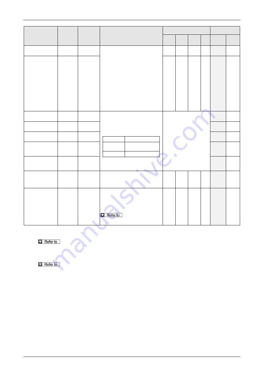
2.1I/O connector input signal
2-3
Signal name
Symbol
Connector
pin No.
(Note 2)
(Note 4)
Contents
Related control mode
EtherCAT
communications
Position Velocity Torque
Full-
close
command
monitor
(Note 3)
External latch input
1
EXT1
*
These signals are used for
touch-probe function or homing
function.
This input can only be set to
a-contact.
The signal width should be 1 ms or
longer then at the time of closing,
and should be 2 ms or longer then at
the time of opening.
It cannot guarantee this value.
EXT1 for Axis A can only be
assigned to SI5 and EXT2 to SI6,
and EXT1 of Axis B to SI1 and EXT2
to SI2.
✔
✔
✔
✔
-
✔
External latch input
2
EXT2
*
✔
✔
✔
✔
-
✔
General purpose
monitor input 1
SI-MON1
*
Used as the general purpose
monitor input.
This input does not affect the
operation, and can be used for
monitoring through,
2321h/2721h
Logical input signa
2323h/2723h
Logical input signal
[expansion portion]
60FDh/68FDh Digital inputs
(Note 1)
-
✔
General purpose
monitor input 2
SI-MON2
*
-
✔
General purpose
monitor input 3
SI-MON3
*
-
✔
General purpose
monitor input 4
SI-MON4
[A or B]
4
(SI4)
-
✔
General purpose
monitor input 5
SI-MON5
[A or B]
14
(SI8)
-
✔
External alarm
clear input
A-CLR
*
Dis arm inputs the alarm.
There are alarms that cannot be
disarmed by this input.
✔
✔
✔
✔
-
✔
Dynamic brake
(DB) switching
input
DB-SEL
*
Switches the dynamic brake (DB)
ON/OFF after stop (when the main
power is off).
Switching is only possible when
main power supply off is detected.
For details, refer to "6.3.3 Sequence at
main power OFF"
✔
✔
✔
✔
-
✔
(Note 1) General purpose monitor input can be used for monitoring, but does not affect driver module operations.
(Note 2) Except for I-
COM, input signal pin assignment can be changed. The pins in “Connector pin No.” column in the table denote
factory default settings. The signal with a pin that is marked with “*” is not assigned by default.
For more information, refer to “2.4.1 Input signal allocation”.
(Note 3) It is possible to monitor the condition of the signals where
“
✔
” is attached to the EtherCAT communication monitor on the table
with 2321h/2721h (Logical input signal), 2323h/2723h (Logical input signal [expansion portion]), 60FDh/68FDh (Digital inputs).
(Note 4) [A or B] in "Connector pin No." column in the table indicates that this signal is accepted by both Axis A and Axis B.
For details, refer to section "2.4.1 Input signal allocation".
Summary of Contents for MINAS A6 Series
Page 10: ...Table of contents x Blank page...
Page 11: ...1 Introduction...
Page 26: ...Introduction 1 16 Blank page...
Page 27: ...2 Interface Specifications...
Page 46: ...Interface Specifications 2 20 Blank page...
Page 47: ...3 Front Panel Specifications...
Page 57: ...4 Basic Functions...
Page 85: ...5 Auto Tuning Functions...
Page 151: ...6 Application Functions...
Page 185: ...7 Protective Functions...
Page 224: ...Protective Functions 7 40 Blank page...
Page 225: ...8 Advanced Safety Functions...
Page 230: ...Advanced Safety Functions 8 6 When test pulse is used Duplex safety input Safety input...
Page 245: ...9 List of Parameters...
Page 281: ...10 Timing Chart...
Page 290: ...Timing Chart 10 10 Blank page...
Page 291: ...11 Power Supply Module...


