


Chapter 5 Internal Memory and I/O Signal
5-12
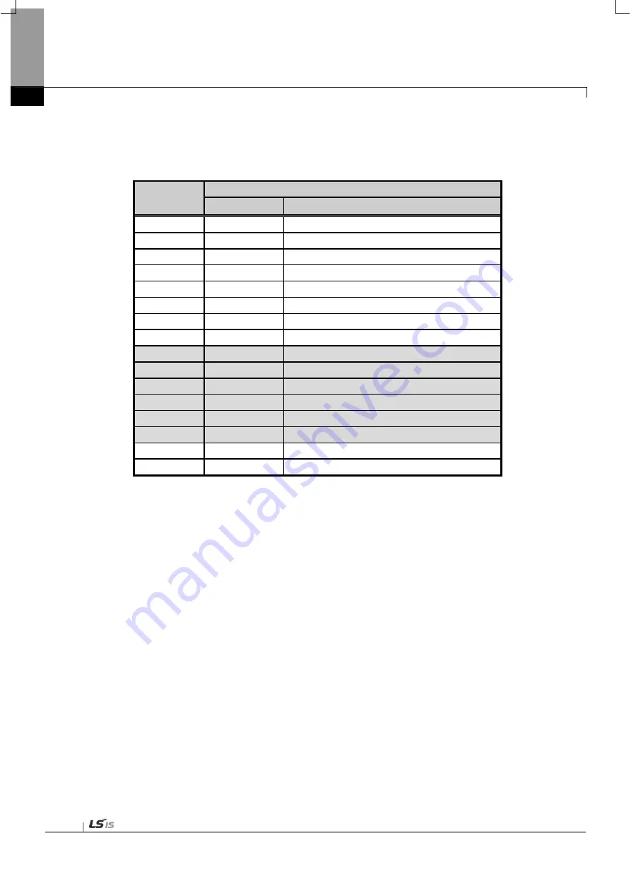
(5) Input Signal
This is the Signal which transfers to basic unit from Positioning Module.
Axis
Signal direction: Basic unit
Positioning module
Input signal
Contents
1 axis
Uxx.00.0
1 axis operation ready
2 axis
Uxx.00.1
2 axis operation ready
3 axis
Uxx.00.2
3 axis operation ready
4 axis
Uxx.00.3
4 axis operation ready
5 axis
Uxx.00.4
5 axis operation ready
6 axis
Uxx.00.5
6 axis operation ready
7 axis
Uxx.00.6
7 axis operation ready
8 axis
Uxx.00.7
8 axis operation ready
-
Uxx.00.8
Not used
-
Uxx.00.9
Not used
-
Uxx.00.A
Not used
-
Uxx.00.B
Not used
-
Uxx.00.C
Not used
-
Uxx.00.D
Not used
Common
Uxx.00.E
Link up/down information
Common
UXX.00.F
Positioning module operation ready
5.2.2 Use of I/O Signal
(1) Axis operation ready signal
(a) For operation ready signal, if positioning module and servo driver are connected through EtherCAT
communication, applicable bit of the connected axis will be on regardless of the operation mode of the
PLC.
(b) EtherCAT communication connection is done through the instruction “XECON” or function block
“XPM_DCON”.
(c) When you disconnection the communication between the positioning module and servo driver by using
instruction “XDCON” or function block “XPM_DCON”, operation ready signal of all axes turn off.
(d) When giving the command to axis, check whether axis operation ready signal is on or not.
(e) For “Uxx.00.zz”, U means PLC CPU’s U device, xx means the location of the positioning module, zz means
the bit of the input signal.
(2) Link up/down information
(a) Link up/down information is on when network cable is connected to the positioning module physically. And
if the cable is disconnected, then it will be off.
(b) If you use it as execution condition contact point of servo connection command (XECON,
Summary of Contents for XBF-PN04B
Page 1: ...Programmable Logic Controller Positioning Module EtherCAT XGB Series XBF PN04B XBF PN08B ...
Page 626: ...Chapter 9 Functions BPS37 setup RS232 and PC connection BPS37 option board LED 9 193 ...
Page 796: ...Appendix3 Dimension A3 1 Appendix 3 Dimension Appendix 3 1 Dimension of XBF PN04B PN08B ...