


Chapter 8 Program
8-4
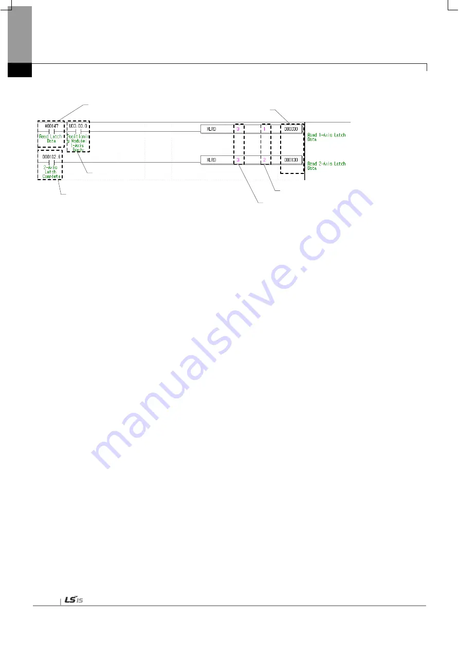
(3) Latch Position Data Read
(a) Conditions for Latch Position Data Read
Conditions to implement the Latch Position Data Read command (XLRD). Fox Axis 1, the Latch Position
Data Read command is always implement if M00147 is On after the axis is connected with the network.
(b) Axis ready
If communication between the positioning module and the servo driver is normal, corresponding signal will
be on. In the example program, latch position data are read if M00147 (Conditions to read latch data) is On
after the axis is connected with the module since Axis 1 ready state (Uxx.00.0) is used.
(c) Latch Completion state
It is the state of “Latch Completion” when an example program of“8.1.2 Read the Current Sate is used. ”It is
on when latch is completed once external latch command signal of the relevant axis is inputted. In case of
Axis 2, the Latch Position Data Read command of Axis 2 i s implemented as soon as D00102.6 (Latch
Completion state) is On.
(d) Position of the module
In order to give a command, you have to specify the position of the positioning module to give a command.
In the example, the positioning module is mounted on the slot 3..
(e) Command axis
When giving a command to each axis, you have to specify an axis to give a command. XBF-PN04(8)B can
supports up to 4(8) axis, 1~4(8) in command means 1-axis ~ 4(8)-axis.
(f) Leading address of the device to save Axis’s latch position data
It is the leading address of the device to save the axis’s latch data value read from the positioning module
by using XLRD. This device can be used on sequence programs. For example, Axis 1’s data count of latch
position is saved on D 00030 and l atch position data 1 ~ 10 ar e saved on D 10032 through D00050 the
example program above. For further information on the saved device, refer to 6.3.56 Latch Position Data
Read command (Command: XLRD).”
(b) Ready for each axis
(a) Condition for read
latch position data
(d) Position of the module
(e) Command axis
(f) Head address of device to
save latch position data
(c) Status of latch completion
Summary of Contents for XBF-PN04B
Page 1: ...Programmable Logic Controller Positioning Module EtherCAT XGB Series XBF PN04B XBF PN08B ...
Page 626: ...Chapter 9 Functions BPS37 setup RS232 and PC connection BPS37 option board LED 9 193 ...
Page 796: ...Appendix3 Dimension A3 1 Appendix 3 Dimension Appendix 3 1 Dimension of XBF PN04B PN08B ...