


Chapter 9 Functions
9-65
(4) T
he number of circular interpolation rotation in absolute coordinate
(a) In case of center point -
specified circular interpolation, absolute coordinate, when setting “Circular
interpolation turns” is more than 1, if you stop it by Dec. stop command and restart interpolation operation, it
doesn‟t operate along the circular arc set again at this stop point and operates along the circular arc set at
the previous start position. That is, in absolute coordinate, center point
– specified circular interpolation, it
operates according to rotation number at start position.
(b) Even if it decelerates and stops, it operates original circular interpolation by restart.
(c) Condition
In the following case, current position changes after deceleration stop command. The number of circular
interpolation rotation is not the number of absolute rotations. It operates by the number of incremental
rotations.
▪ After executing positioning command except for current step indirect start (Directing start, Jog operation,
Inching operation, Sync. operation, etc),
▪ After executing “Current position change” command
▪ After executing “Servo off” command
[ Example ] operates center-point circular interpolation, absolute coordinate with axis 1 (main axis), with
axis 2 (sub axis)
■ Starting position (100, 500), Target position (600, 300), Auxiliary position (600, 500),
Direction of rotations: CW, operation is as follows:
■ Example of setting XG-PM
▪ Main axis (axis 1) operation data
Step
No.
Control
Method
Operation
method
Target
position
[pls]
Operation
Speed
[pls/s]
Acc.
No.
Dec.
No,
M
code
Dwell
time
Sub axis
setting
Circular
interpolation
Auxiliary point
Circular
Interpolation
mode
Circular
interpolation
turns
Helical
interpolation
1
Absolute, circular
interpolation
Single,
End
600
1000
No.1
No.1
0
100
Axis 2
600
Center point,
CW
3
Do not use
▪ Sub axis (axis 2) operation data
Step
No.
Control
Method
Operation
method
Target
position
[pls]
Operation
Speed
[pls/s]
Acc.
No.
Dec.
No.
M
code
Dwell
time
Sub axis
setting
Circular
interpolation
Auxiliary point
Circular
interpolation
mode
Circular
interpolation
turns
Helical
interpolation
1
Absolute, single-
axis position
control
Single,
End
300
0
No.1
No.1
0
0
None
500
Middle point
0
Do not use
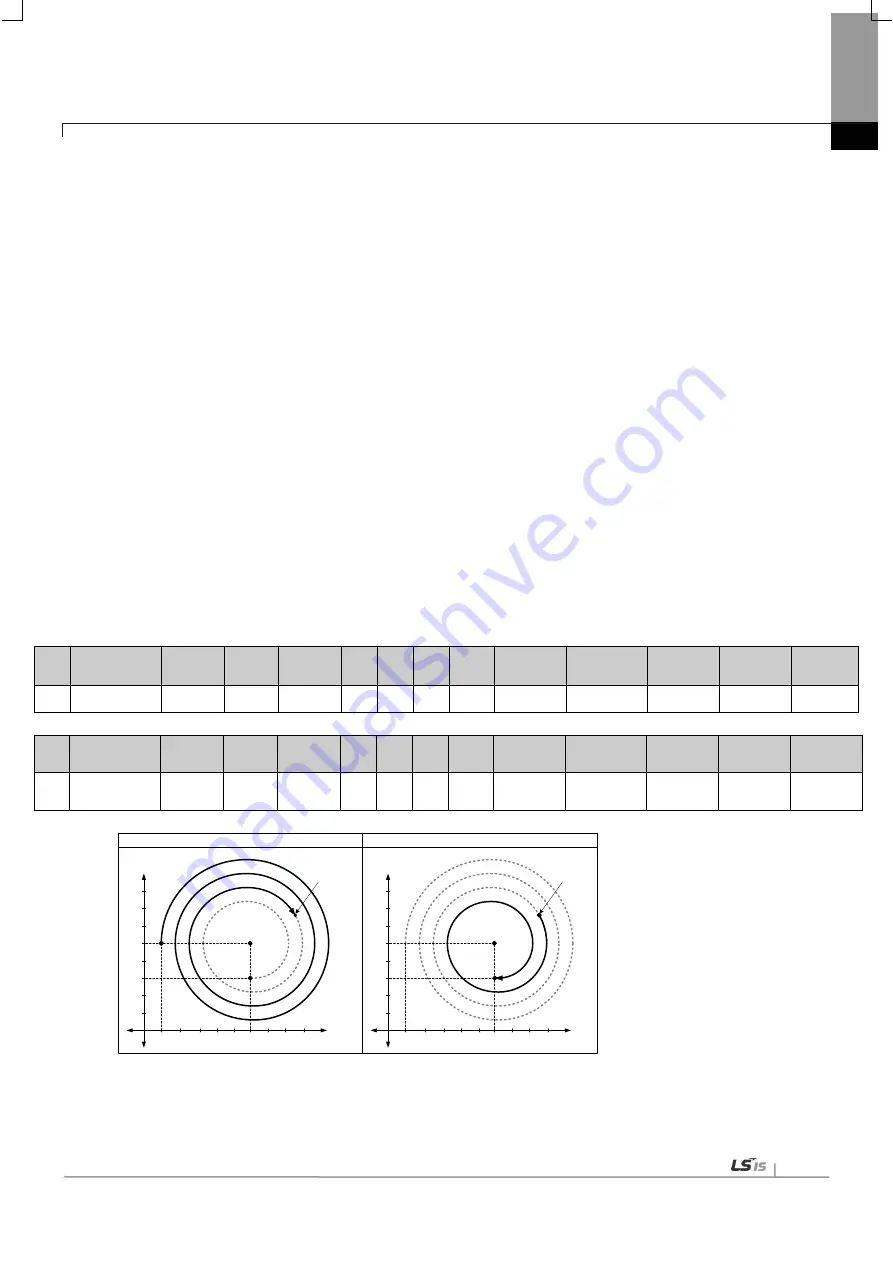
■ Operation pattern
When you restart the same step number after stopping it by Dec. stop command, it doesn‟t rotate 3 times at the
stop position. Since it rotated 2 times previous operation, it executes circular interpolation of one time rotation to go
target position.
Forward of
sub axis
Forward of
main axis
0
Centerpoint
Starting
position
100
600
500
100
Forward of
sub axis
Forward of
main axis
0
Stop by
「
deceleration
stop
」
Starting
position
100
600
500
100
Restart by
「
directing start
」
Centerpoint
Target
position
Target
position
300
300
「Deceleration stop」during of operation circular interpolation
Restart of circular interpolation operation
Summary of Contents for XBF-PN04B
Page 1: ...Programmable Logic Controller Positioning Module EtherCAT XGB Series XBF PN04B XBF PN08B ...
Page 626: ...Chapter 9 Functions BPS37 setup RS232 and PC connection BPS37 option board LED 9 193 ...
Page 796: ...Appendix3 Dimension A3 1 Appendix 3 Dimension Appendix 3 1 Dimension of XBF PN04B PN08B ...