


Chapter 6 Command
6-25
(e) D device signal (axis1 in Operation, etc) which used in the example above is an assumption that saving the
axis state value in D device area with XSRD command.
(f) In order to use user CAM operation, you have to set CAM block number as 9.
(g) In the case of user CAM operation, it is possible to change the user cam data with write variable data
command during operation.
(h) For detailed information on user CAM operation, refer to “94.4. user CAM operation”.
6.3.18 Main axis offset-designated CAM Operation (Command : XCAMO)
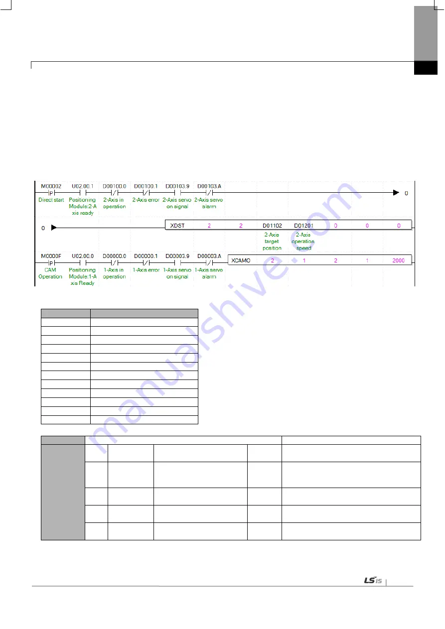
(1) Program
(2) Description
Device
Description
M0000F
axis1 cam operation input
M00002
axis1 direct start input
U02.00.0
axis1 ready
U02.00.1
axis2 ready
D00000.0
axis1 in operation
D00000.1
axis1 error state
D00003.9
axis1 servo on signal
D00003.A axis1 servo error
D00100.0
axis2 in operation
D00100.1
axis2 error state
D00103.9
axis2 servo on signal
D00103.A axis2 servo error
Command
XCAMO
Cam Operation
Operand
OP1
Slot
Constant
WORD Slot No. installed with positioning
module
OP2
Axis
PMLK,constant,D,Z,R,ZR WORD
Command axis
XBF-PN04B: 1axis~4axis
XBF-PN08B:1axis~8axis
OP3 Main axis
PMLK,constant,D,Z,R,ZR WORD Main axis (1 ~ 8 : axis1 ~ axis8, 9 :
Encoder1, 10:Encoder2)
OP4 Cam Block PMLK,constant,D,Z,R,ZR WORD Cam data block to apply to operation (1
~ 9)
OP5 Main axis
offset
PMLK,constant,D,Z,R,ZR
DINT
Main axis position to start CAM
operation
※
PMLK means P, M, L and K areas.
Summary of Contents for XBF-PN04B
Page 1: ...Programmable Logic Controller Positioning Module EtherCAT XGB Series XBF PN04B XBF PN08B ...
Page 626: ...Chapter 9 Functions BPS37 setup RS232 and PC connection BPS37 option board LED 9 193 ...
Page 796: ...Appendix3 Dimension A3 1 Appendix 3 Dimension Appendix 3 1 Dimension of XBF PN04B PN08B ...