


Chapter 8 Program
8-101
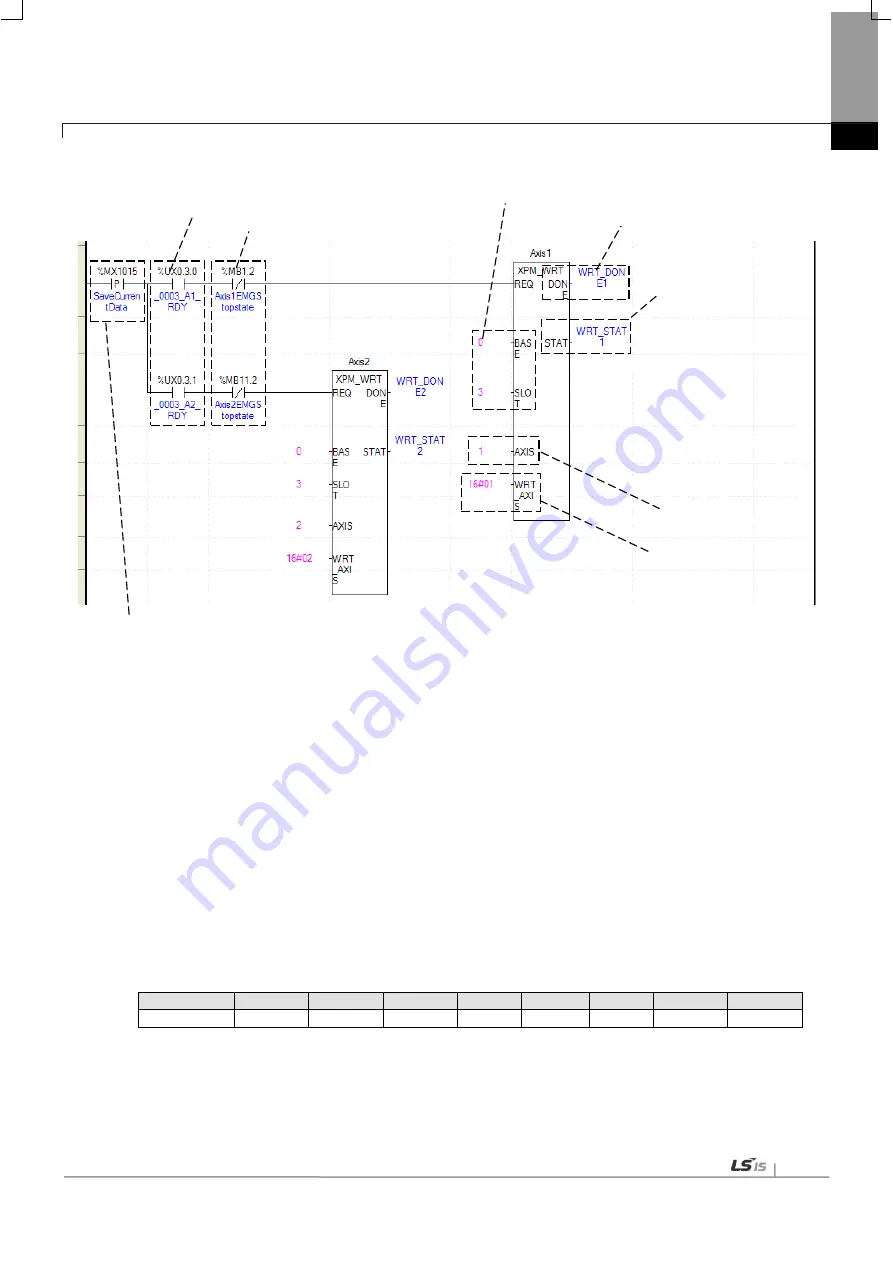
(4) Saving Current Data
(a) This is the condition for Saving Current Data
This is the condition for Saving Current Data Command (XPM_WRT). When current saving data operated,
those values of module parameter and operating data would be saved in MRAM. Therefore configuration of
Ram or Ram Teaching would be constantly saved whether power is on or not.
(b) Axis ready
If communication between the positioning module and the servo driver is normal, corresponding signal will be
on.
(c) Emergency Stop by each axis
According to exercise from “Chapter 8.2.2 Current State Reading,” it is a signal of “State of Emergency Stop”
for each axis. It turns on when it is Emergency Stop. Emergency Stop can not be configured while it is running
hence configuration will only be configured when it is not running.
(d) Address of Positioning Module
In this example, Positioning Module is installed at the 3 slot of 0 bases.
(e) Axis of command execution
You can set an axis for Parameter Setting. XBF-PN04(8)B supports for 4(8) axes. In the “execution of axis”
from the configuration of Parameter Setting, you can set a value for axis1 through axis4(8).
(f) Saving by axis
Configure current data operation setting. Choosing axis are configured follow by below table. Therefore even if
those axis are not operated as it programmed, saving axis can be saved in Array. The data of operated axis
saved in MRAM, which make constantly stable whether its power is on or not.
15 ~ 8 Bit
7Bit
6Bit
5Bit
4Bit
3Bit
2Bit
1Bit
0Bit
N/A
axis 8
axis 7
axis 6
axis 5
axis 4
axis 3
Axis 2
axis 1
(g) State of Operation complete
If function block is completed without error, “1” will be outputted and m aintain “1” until the next operation. If
error occurred, “0” will be outputted.
(h) Error State
This is the area that output error no. if there are errors in operation of function block.
(a) Condition for saving current data
(b) Axis ready state
(c) EMG. stop state
(d) Position of the module
(g)Completion state
(h) Error state
(e) Command axis
(f) Axis to save
Summary of Contents for XBF-PN04B
Page 1: ...Programmable Logic Controller Positioning Module EtherCAT XGB Series XBF PN04B XBF PN08B ...
Page 626: ...Chapter 9 Functions BPS37 setup RS232 and PC connection BPS37 option board LED 9 193 ...
Page 796: ...Appendix3 Dimension A3 1 Appendix 3 Dimension Appendix 3 1 Dimension of XBF PN04B PN08B ...