background image

187 


7.05.4 Using Symmetrical Mirror to Complete the Trace 


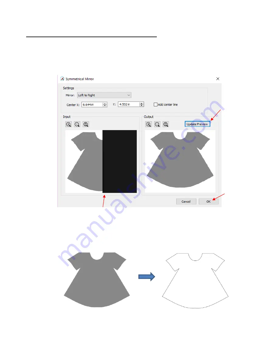
The final step to complete the dress involves making a mirror image copy and then welding it to the original.  


Select the dress and go to 

Effects>Symmetrical Mirror

. Increase 

Center X 

or drag the black rectangle 

to the right and click on 

Update Preview

. Continue adjusting 

Center X

 until the image is to your 

satisfaction: 


After clicking on

 OK

, the dress is complete and the original image is no longer needed. Turning on 

Show Outlines Only

 on the 

Document Panel

 confirms that the symmetrical copy has been welded to 

the original: 


Other applications for 

Symmetrical Mirror

 are covered in 

Section 9.23.


Click on 

Update 

Preview 

after each 

change 

Click on 

OK


when done 

Drag black rectangle 
to desired location 
(

Center X

Summary of Contents for KNK Force

Page 1: ...r 13 covers the Force rotary tool It s not practical to print this entire manual because It s a waste of paper and ink if you only ever need certain sections The live links to videos blog posts produc...

Page 2: ...ontrolling Where Shapes Will Cut 21 2 02 3 Selecting the Tool to be Used for Cutting 21 2 02 4 Determining the Cut Settings 22 2 03 CUT SETTINGS DETAILS 23 2 03 1 Tool and Replace Tool 23 2 03 2 Mult...

Page 3: ...CTS AND PAGES 61 3 12 HELP RESOURCES 62 4 SCAL HANDLING FILES AND ORGANIZING LAYERS 64 4 01 OPENING FILES 64 4 01 1 Opening a New File Project 64 4 01 2 Opening an Existing SCUT File 64 4 02 SAVING SC...

Page 4: ...5 05 1 Resizing 96 5 05 2 Scaling 98 5 05 3 Auto Fit 99 5 06 ROTATING 100 5 07 SKEWING AND DISTORTING 101 5 07 1 Skewing 101 5 07 2 Distorting 102 5 08 MIRRORING AND FLIPPING 102 5 09 LOCKING AND UNLO...

Page 5: ...04 FOUR MODES OF TEXT 137 6 04 1 Type Tool 137 6 04 2 Vertical Type Tool 137 6 04 3 Type on Path Tool 138 6 04 4 Type on Arch Tool 139 6 05 TEXT SETTINGS 140 6 06 OTHER TEXT EDITING 142 6 07 CREATING...

Page 6: ...Image for Manual Tracing 183 7 05 2 Manual Tracing Using the Draw Tool 184 7 05 3 Editing the Trace 185 7 05 4 Using Symmetrical Mirror to Complete the Trace 187 8 SCAL EDITING 188 8 01 SIMPLIFY 188...

Page 7: ...for Rhinestone Pattern Design 237 9 12 2 Rhinestone Outline 238 9 12 3 Rhinestone Fill 240 9 12 4 Editing Rhinestone Designs 241 9 12 5 Adding an Outline to a Rhinestone Design 242 9 12 6 Using Purch...

Page 8: ...AT IS A PRINT AND CUT PNC 340 11 02 WHAT IS A PNC CALIBRATION 341 11 03 CAMERA CALIBRATION PROCEDURE 341 11 03 1 What You Need for Calibrating 341 11 03 2 Preparing the Calibration File 341 11 03 3 En...

Page 9: ...378 SUGGESTED ENGRAVING SETTINGS FOR FORCE ROTARY TOOL1 379 APPENDIX A SCAL KEY BOARD SHORTCUTS 380 APPENDIX B KNK FORCE AND SCAL TROUBLESHOOTING 386 B1 COMMUNICATING ISSUES 386 B2 OPERATING ISSUES 3...

Page 10: ...section and Chapter 2 before attempting to use the blade holder in your Force If you have already been using SCAL with your KNK Force you can use this user manual as a reference book 1 02 Safety and W...

Page 11: ...ck to KNK USA for repair The one year parts and labor warranty covers manufacturer s defects only and does not include normal wear and tear If warranty work is required the owner is responsible for sh...

Page 12: ...SCAL Facebook Page MTC and SCAL Facebook Group SCAL Users Yahoo Group An online training program with over 4 hours of videos is available at this link Sure Cuts a Lot 4 Beginner Class 1 06 Setting up...

Page 13: ...e mode Note the arrow at the top of the cutting mat This indicates Portrait mode and how the mat will be inserted into the Force Indicates the direction the mat is fed into the cutter In Portrait mode...

Page 14: ...n the Cut Settings window either Go to Cutter Cut with KNK Force Click on the Cutter icon on the Toolbar at the top The Cut Settings window will open Under Connection it should read TCP IP This is the...

Page 15: ...requently Note that if the test pen isn t working you can insert any regular pen or marker directly into the grip on the Force Make the following changes in the Cut Settings window Place your paper on...

Page 16: ...ntially the same as how you set it in C3 o The same shortcut keys previously listed can be used to move in larger or smaller increments o Once the head is in position click on OK Use all of the same s...

Page 17: ...you are cutting The 45 blade red cap should be used to cut vinyl paper cardstock Dura lar Mylar iron on transfer vellum The 60 blade blue cap should be used to cut chipboard Grungeboard stiffened felt...

Page 18: ...circle has cut too deeply Once you have optimized the settings for the ring try another more detailed shape such as the asterisk If you are cutting across the width of the material also test a wide t...

Page 19: ...users and KNK dealer Utilize these resources A recommended list was presented on the first page Please follow a few rules of etiquette out of respect for those who are eager to assist This saves both...

Page 20: ...still have the option to hide those other shapes as in the prior option but this could be quicker if there are a lot of shapes to turn off For shapes you do not wish to cut change the Cut Line Type on...

Page 21: ...precisely in the location on the paper as they are located on the screen Note that raster images JPG BMP PNG etc will need to be traced first so that cut lines are created Refer to Section 7 03 for t...

Page 22: ...gs for your material use the flow chart in Appendix D4 to test cut your material and determine optimum settings The following table summarizes the settings and shows the typical range you can expect t...

Page 23: ...ther words leave Tool set to 1 left and then enter all settings to be used by the left side tool When both heads will be used after entering the left side settings change Tool to 2 right and then ente...

Page 24: ...the material as well as the height where the Z Origin is set More information on determining the CD ED is presented in Sections 13 04 13 05 When engraving or embossing the CD ED is the depth to which...

Page 25: ...set quite high e g at 40 If you are cutting a dense material such as thick chipboard or any time you are using the blue capped blade a lower Plunge Speed such as 20 can help protect the blade from too...

Page 26: ...some cutting programs Overcut is not a separate setting but rather automatically calculated and applied based on the Blade Offset entered However in SCAL you enter an actual Overcut setting and shoul...

Page 27: ...added select it from the menu and then a button will appear Clicking on that button will then remove it from the list 2 05 Blade Tension BT Inside the KNK Force blade holder is a large spring that is...

Page 28: ...lways a good idea to do a small test cut before cutting a large project Select a shape from the Library in SCAL to use 2 Press the material to a clean and sticky mat unless a rolled material is being...

Page 29: ...commended Blade Tension settings 7 Go to the Cut Settings window and click on Replace Tool and follow the on screen instructions Set the Z Origin with the tip of the blade touching the top of the mat...

Page 30: ...erfectly acceptable for the type of cutting you do Therefore it may not even be necessary to do this particular calibration However if you do want to make sure your shapes are cut precisely the follow...

Page 31: ...uare select it and then click on the Position Size icon to display that panel The square will be 1 x 1 or 25 4 mm x 25 4 mm Change the size W and H to the largest size that will fit on the paper you h...

Page 32: ...h a metric ruler you should be able to more accurately read the exact measurements Write those measurements onto your sheet Go to Cutter Cutter Settings In the top left corner of that window you will...

Page 33: ...nd click on Save If after testing again you find that the sizing is still slightly off then just repeat again Note that in the calculations the second time instead of using 1 00 for the Current X Reso...

Page 34: ...NK Force1 Material Type and Thickness Material Brand Source Color etc Blade BT P SD CD ED CS Other Settings and Comments 1 2015 2019 Sandy McCauley All Rights Reserved BT Blade Tension P Passes SD Sta...

Page 35: ...cutting Place in a freezer for 1 minute after cutting and before weeding Cardstock AC Textured 80lb Hot Pink R 2 2 70 70 25 Tendency to tear at corners so 2 passes at ED 70 cleaner than 1 pass at high...

Page 36: ...d s Eye Designer My Girl R 2 5 1 90 25 Cardstock Neenah 65lb White R 2 1 60 25 Cardstock Neenah 80lb Solar White smooth R 2 2 50 50 25 2 passes at a lower CD gave cleaner cutting than 1 pass at a high...

Page 37: ...rigin set based on mat Chipboard 0 02 Cereal Box Cracker box B 2 1 120 15 Printed side face down Z axis origin set based on mat Chipboard 0 02 Cereal Box NesQuick Family Size B 4 1 125 25 Printed side...

Page 38: ...een Gold Silver R 2 1 90 30 color side up Freezer Paper Reynolds R 1 1 7 25 mat sprayed with 404 ruler grip adhesive Glitter Cardstock chipboard wt Fabrique Red R 3 2 47 95 20 PS 30 This is sold at Jo...

Page 39: ...ted Leather artific White Y 2 5 2 15 15 25 Cuts like butter Leather 0 065 1 6 mm Dk Brown B 1 5 3 20 60 15 PS 10 Applied Contact shelf liner on the back to protect the mat The leather was purchased at...

Page 40: ...an vary in both thickness and density Start with conservative settings and move up until a clean cut is attained May require even higher SD ED Rhinestone Hartco 425 w o the mat Green B 3 2 80 80 25 Cu...

Page 41: ...ical Translucent R 1 1 30 25 100 cotton Vellum 0 003 Worldwind Grape R 2 1 20 25 Vellum 0 0035 Lt Yellow R 2 1 20 30 Vellum 0 004 Teal R 2 1 25 25 Vellum 0 004 The Paper Company Translucent R 2 1 25 2...

Page 42: ...reen Dark Green Royal Blue Black Vinyl Metal Fx Contact silver R 1 1 20 25 Vinyl Premium Oracal 951 R 1 1 20 25 Vinyl Printable on the mat White R 1 1 25 25 Vinyl Printable w o the mat White R 1 1 25...

Page 43: ...and internal lines Tiling splitting large designs into sections for cutting Duplicate cutting setting up a grid of repeats in the cutting window Cut by color Cut by layer use different settings as ne...

Page 44: ...ersion of SCAL you installed matches the registration you purchased You can verify this by going to Help About Sure Cuts a Lot If the wrong version is installed uninstall this current version and down...

Page 45: ...activate Go to the new computer and activate SCAL If you need to activate your Serial Number on both a PC and a Mac go to Help Support Technical Support and click on Contact Support Team 3 01 3 Instal...

Page 46: ...els will need to be separately selected later in the Cut Settings window Click on Done to save and close the window Now when you are ready to cut the cutter you use will be selected by going to Cutter...

Page 47: ...ting mat which will be written with lower case normal type The Rulers can be toggled on and off by right clicking on the screen and selecting Show Rulers Note that when hiding the rulers click again o...

Page 48: ...click on the thumbnail for that shape or drag the shape onto the Cutting Mat Note there are other categories within the Library listed on the left side Check out the various subfolders of shapes as t...

Page 49: ...instructions can be found under Help Help Clicking on the icon for any the seven panels will open that panel To expand a panel for easier viewing click on the small icon to the right of the panel name...

Page 50: ...ce between Advanced and Basic is the former has the Layers Panel open To switch to other panels click on the icons along the right side If there s a particular panel you access often then you can crea...

Page 51: ...lished by having it either opened or closed and then saving it along with your preferred Properties Panel layout To save workspace changes go to Window Workspace Save Workspace A window will open and...

Page 52: ...Document Panel The Document Panel contains settings for the Cutting Mat which serves as a design area for the software as well as to indicate in some cutting modes where the shapes will be cut 3 06 1...

Page 53: ...u and will be listed under Presets when you return to the Custom Mat Size window To remove a custom Cutting Mat from the menu go back to the Custom Mat Size window and select the mat under Presets Cli...

Page 54: ...the Documents Panel The units can also be changed in either of the following locations Go to View Ruler Units Right click on the screen and select Ruler Units 3 06 4 Show Grid The mat grid can be tog...

Page 55: ...up cards from scratch They can be added to the Cutting Mat in two ways By dragging your mouse from the horizontal or vertical rulers on the screen By manually adding in the Guidelines Edit window You...

Page 56: ...of filled shapes on the Cutting Mat You can also change the opacity of individual shapes versus all shapes Refer to Section 5 14 5 3 06 7 Show Outlines Only This option determines whether shapes are d...

Page 57: ...er Cutter Cutter Settings Refer to Section 8 06 1 3 06 10 Show Page Color The default color of the Cutting Mat is a grayish white To change the color to any other desired color mark the option for Sho...

Page 58: ...nd mark your preferences based on the following options Grid selected shape will snap to the grid lines Guidelines selected shape will snap to guidelines refer to Section 9 03 Objects Bounds selected...

Page 59: ...ved For now note the following preferences that do relate to the material covered so far These should be self explanatory based on their names If you click on the Edit tab more preferences are listed...

Page 60: ...zoom in on a selected shape or shapes use one of the following Click on the icon while the Zoom in Tool is activated see prior screenshot Use the shortcut Ctrl Shift on a Mac Control Shift Go to View...

Page 61: ...Project Bar is located right above the Ruler and shows what projects files are open and have been named new projects that have been started but not named and an option to open a new project Clicking...

Page 62: ...f you mark the Show Page Color option on the Document Panel If you change your mind and want to edit the Name and or Color either go to Page Page Properties or double click on the Page Name and the sa...

Page 63: ...tutorials Go to Help Support Technical Support for the following o Contact the SCAL team o Retrieve your serial code o Download latest updates o Access the forum o Access tutorials Other online suppo...

Page 64: ...ettings These settings can be modified later if needed using the Document Panel Note that as of SCAL5 you can have more than one project open at a time 4 01 2 Opening an Existing SCUT File An existing...

Page 65: ...hift S for save as Go to File Save Project or File Save Project As If you ve made changes and wish to save under a different file name choose File Save As Name the file choose a location and click on...

Page 66: ...rea on the right side To add one of these shapes to the Cutting Mat either Click on the shape and it will be placed in a certain location on the Cutting Mat Drag the shape to a desired location on the...

Page 67: ...vorites from the popup menu This popup menu also has these options o Delete File only active in the My Designs folder o Reveal File opens the location on your computer where file is stored o Instructi...

Page 68: ...the Choose Folder button will activate and clicking it will bring up this window where you can browse your computer to locate an existing folder of SVG files Refresh Add Folder Click on My Designs De...

Page 69: ...fter deleting files you will need to click on the Refresh icon to update the thumbnail images To delete a folder select it and then do one of the following o Click on the Delete Folder icon o Right cl...

Page 70: ...selected you can click on the icon to add that font to your Favorites folder For alternative methods for selecting fonts refer to Section 6 02 4 03 3 Projects Tab The Projects tab is similar to the S...

Page 71: ...cts for easy access Once you click on My Projects the icons above the folder menu will become active Add subfolders The projects in the above screenshot have been added to My Projects but are not in s...

Page 72: ...lick on the Delete Folder icon o Right click and select Delete Folder from the popup menu To rename a folder right click and select Rename Folder from the popup menu 4 04 Layers Panel Because of the i...

Page 73: ...different templates such as a fill that will be done in one color of rhinestones and an outline in another color Other benefits of assigning shapes to specific layers include Ability to select with on...

Page 74: ...he Layer Properties window Here you can change the name of that layer as well as some other settings Note that the color assignment is for use on the Layers Panels only It doesn t change the color of...

Page 75: ...ck Unlock icons can be individually changed In this example some basic shapes have been used for a clearer understanding 4 04 3 Creating Folders and Moving Layers As mentioned in Section 4 04 1 each n...

Page 76: ...s moved into an existing folder The way to control where the layer lands is by moving it straight up and down or by dragging a little to the left while moving it up and down If you drag a layer withou...

Page 77: ...t of an existing folder into other folders In this example the yellow centers of the flowers in the layers named Flower 1 and Flower 2 can be similarly dragged and dropped into the Yellow Shapes folde...

Page 78: ...d Ungrouping are covered in Section 5 11 4 05 The eshape Store 4 05 1 Importing from the eshape Store The eshape Store is an online shopping site linked within SCAL Cutting files and fonts can be purc...

Page 79: ...wing Download Manager window will open and the files you purchased will begin downloading Now open the Library to access the eshape Store files Depending on the file type the downloaded files will eit...

Page 80: ...er and click on Show Orders Then click on the Download icon 4 05 2 Exporting to the eshape Store To freely share your own SCAL creations go to File Share Project The following window will open If any...

Page 81: ...keywords based on what other SCAL owners might use to locate a file like yours Description Enter information about the file that will help an owner know if it s what they might want or need After com...

Page 82: ...es to include the start of an embedded YouTube video link o Alternatively you can link to an MP4 video located elsewhere Finally click on the Instructions tab and enter any instructions for the projec...

Page 83: ...ctor parts of a PDF will import into SCAL AI Adobe lllustrator common format due to the popularity of Adobe Illustrator EPS another common export format for many vector programs Nine embroidery file f...

Page 84: ...iginal source of the vector file double lines may exist which will result in cutting a design twice This is usually due to the source program having a Stroke width applied to the lines Therefore any t...

Page 85: ...d PLT are vector formats The others are raster If there are only certain shapes in the file that you want to export you have two options Select those particular shapes before exporting and then mark a...

Page 86: ...use the image in a digital scrapbooking program You want to print a PNC project from a printer without SCAL installed If you choose any of the raster export formats the same window will open offering...

Page 87: ...rt entire folders of SVG files at one time 4 07 4 Exporting in PLT Format PLT files were originally developed for HP plotters They are also used by some of the cutters outside of the hobby world The E...

Page 88: ...CAL2 by going to File Send to Sure Cuts A Lot 2 You will need both versions of SCAL open at the time Because PLT files are usually sent directly to the plotter or cutter the settings are specific to t...

Page 89: ...rious shapes hold down the left mouse button on the Rectangle icon on the Tools Panel and then select the desired shape from the popup menu Once a different shape is selected that shape s icon will th...

Page 90: ...rtions resulting in a triangle in which the height will equal the width 5 01 5 Polygon After selecting the Polygon shape drag the left mouse button to form a polygon In the Tool Options a Polygon corn...

Page 91: ...ns four settings will appear Turns Number of rotations around the center Divergence Tightness of the spiral larger looser smaller tighter Inner Radius Starting point of the spiral Clockwise Whether sp...

Page 92: ...shape aka marquee select A third way hold the Shift key and marquee select just a portion of the shape A fourth way click on the layer which contains this shape 5 02 1 Basic Selection Handles Once sel...

Page 93: ...t more than one shape Select the first shape and hold down the Shift key while clicking on additional shapes Drag the mouse marquee select to encompass the shapes Always make sure you start clearly ou...

Page 94: ...apes in the current project Use one of the methods from Section 5 02 to select all shapes Then delete using any of the prior options listed for deleting a selected shape You can also delete a layer of...

Page 95: ...changed by going to Edit Preferences and then selecting the Edit tab This window also offers the option to force shapes to remain within the boundaries of the Cutting Mat while being moved with the m...

Page 96: ...ing With the shape selected use your mouse to drag the lower right corner of the shape to freely resize If you want to keep the width and height proportional hold the Shift key down before dragging th...

Page 97: ...Panel You will need to hold the Shift key to maintain proportions when resizing by dragging the lower right corner If you need to make the shape an exact size then enter the dimension in the W or H b...

Page 98: ...ion change or percentage will be applied as if there were no bounding box around the shapes o For example take three 1 inch squares that are 1 inch apart from one another Select all three and apply a...

Page 99: ...11 875 x 11 875 If the circle is placed on a 15 x 15 mat then it resizes to 14 85 x 14 875 However if the circle is placed on letter size mat 8 5 x 11 then it becomes an oval A practical example migh...

Page 100: ...bottom of the screen will indicate the current degree of rotation Note the Status Bar will continue to show the last degree of rotation until another shape is selected and rotated A selected shape can...

Page 101: ...to skew the shape With the shape selected open the Rotate window by using one of these two methods o Right click and select Transform Rotate o Go to Object Transform Rotate Then switch from Angle to S...

Page 102: ...ol can be applied to anything 5 08 Mirroring and Flipping To horizontally mirror a shape select it and then use one of the following Right click on the screen and select Transform Flip Horizontal Mirr...

Page 103: ...he shape or folder on the Layers Panel and click on the Lock icon or double click and uncheck the Lock option To unlock all locked shapes use any of the following options Right click on a selected unl...

Page 104: ...s Menu icon and select Show Hide Toggle All Layers 5 11 Grouping and Ungrouping 5 11 1 Group The Group function is used to combine shapes into a new folder on the Layers Panel so that they can be more...

Page 105: ...ing applied to the same word Bob to separate the internal closed paths also called child shapes from the external paths also called parent shapes Before applying Ungroup After applying Ungroup Before...

Page 106: ...le shape This is basically the opposite function to Break Apart After selecting two or more shapes the Merge function can be accessed in either of the following ways Go to Object Merge Press Ctrl Shif...

Page 107: ...yers was presented and could be used here to change the order of the shapes However another way to reorder these shapes is to select one and then access the Arrange functions using one of the followin...

Page 108: ...if any of the other layers had been locked or hidden the movement of the triangle would have been the same In other words if the red heart had been hidden and or locked the triangle would still have e...

Page 109: ...uts This can be helpful in designing a project and also in print and cut applications To open this panel click on the Fill Stroke icon on the Properties Panel Shapes can be filled with nothing a solid...

Page 110: ...rough the shape if the Show Grid option on the Document Panel is turned on 5 14 2 Color Fill From the Fill menu select Color and then click on the color box to the right The following Color Picker win...

Page 111: ...hange so you can immediately see the effects Once you have the color you wish to use click on OK However if you want that same color available to select again within this same file click on Add to cus...

Page 112: ...My Patterns select common raster file formats e g BMP PNG JPG The pattern settings can be used to modify how the pattern appears in the filled shape for example The other tab Load image can be used to...

Page 113: ...lowing window where a gradient can be designed Type Choose Linear for a left to right gradient Choose Radial for a center outwards gradient Click here to load a raster file Uploaded image Pattern sett...

Page 114: ...ou inadvertently add a marker or decide you don t want one or more of the new ones drag the marker downward and it will be removed Position The Position value is a location from 0 to 100 and applies t...

Page 115: ...name this Preset To access your saved Gradient Presets click on the Presets tab and the menu will appear 5 14 5 Opacity Just below the Fill setting is Opacity Decreasing the Opacity setting will make...

Page 116: ...ve a Stroke assignment using one of the following choices None The shape will not have an outline Note that if you also choose None for the Fill then you will not be able to see the shape at all unles...

Page 117: ...u choose Pen Color and then click on the box to the right the Choose Pen Color window opens o Select the desired color from the menu and click OK You also have the option to create your own custom Pen...

Page 118: ...he same menu where you can add new colors are options to Remove Color or Rename Color Before you can use these options you will need to close and reopen SCAL Opacity Decreasing the Opacity setting wil...

Page 119: ...l difference if the Stroke Width is small Thus to illustrate Join a Stroke Width of 20 will be used End Caps Unclosed shapes such as lines and arcs can have the Stroke shape on the ends changed simila...

Page 120: ...apes In the event you decide the stroke should be its own shape select the shape and go to Path Stroke to Path You can now drag the stroke shape away from the original If you want the new outline shap...

Page 121: ...s Stroke Width or Opacity will not be copied onto the selected shape On the other hand if the Fill is a pattern or gradient it will be copied You can also fill multiple shapes at once Note however tha...

Page 122: ...ake multiple copies refer to the Duplicate function described later in this section 5 17 3 Pasting from the Clipboard There are three Paste functions in SCAL Paste pastes the shape offset slightly 0 2...

Page 123: ...on how this function can be used to create a border There is also a Duplicate Rotated function to arrange the duplicates in a circular formation Because this is more typically used for design purpose...

Page 124: ...e Align to Page is checked Select To Page on the Position Size panel With the shapes selected the horizontal alignment options are Align Left aligns shapes along the left side of the Cutting Mat Align...

Page 125: ...ure the alignment mode is set to Align to Selection This is done by either making sure To Selection is chosen on the Position Size panel or by going to Object Alignment and making sure Align to Select...

Page 126: ...Mat or you can Distribute to Selection selected shapes There s also a third called Distribute to Selection Below which distributes based on whatever shape is positioned at the lowest level on the Laye...

Page 127: ...rple arrows indicate equal spacing With the shapes selected the horizontal distribute options are Distribute Left spaces shapes so that the left sides of each shape are the same distance apart Distrib...

Page 128: ...ape are the same distance apart Distribute Center Vertically spaces shapes so that the centers of each shape are the same distance apart Distribute Bottom spaces shapes so that the bottom sides of eac...

Page 129: ...selected the horizontal distribute options are Distribute Left spaces shapes so that the left sides of each shape are the same distance apart Distribute Center Horizontally spaces shapes so that the...

Page 130: ...pplications to share and the developer hasn t responded to my request for assistance Thus I can only explain what happens when you apply it Maybe one of our readers will figure out a great use for it...

Page 131: ...e the purple circle that s both furthest to the right and furthest towards the bottom equal to 3 in size instead of just 1 and then apply the same Distribute options Distribute Left The new location f...

Page 132: ...circle in both of the opposite directions In other words when applying Distribute Left the purple circle was the rightmost shape When applying Distribute Top the purple circle was the bottommost shape...

Page 133: ...ck the Text Settings icon on the Properties Panel to open the Text Panel Select from the Font drop down menu Go to Text Font Click on the Fonts tab in the Library refer to Section 4 03 2 If you are lo...

Page 134: ...ction only to more easily decide which ones you might like to use Expand the window and highlight those you want to further compare After scrolling through fonts and highlighting only those of further...

Page 135: ...le sample you can then click on Change Font The text will now be changed to the new font 6 02 3 Temporarily Installing a Font If you want to load a new font that s not already installed on your comput...

Page 136: ...font you select from the drop down menu If you have no plans to edit the text then you can avoid the message by converting text before saving the file To do this select the text and apply one of the...

Page 137: ...new text at that location When done either press the Esc key or click on the Select icon on the Tools Panel 6 04 2 Vertical Type Tool Hold down the mouse button on the Type Tool icon on the Tools Pan...

Page 138: ...ool icon on the Tools Panel and select the third choice Type on Path Tool Click on or inside the shape and begin typing In the Tools Options a setting appears which allows you to move the start point...

Page 139: ...n imaginary circle Hold down the mouse button on the Type Tool icon on the Tools Panel and select the last choice Type on arch Click anywhere on the Cutting Mat and begin typing In the Tools Options t...

Page 140: ...instructions in Section 8 04 Then click on the Selection Tool icon at the top of the Tools Panel With the text selected you can now change any of these various settings and the changes will immediate...

Page 141: ...then try applying again o Instead of using Bold you can use Effects Shadow Layer refer to Section 9 05 or Path Offset Path Section 8 05 o Instead of using Italic you can use the Skew function refer to...

Page 142: ...her and can result in overlapping Leading Changes the spacing between lines of text V Offset Raises or lowers a line of text or more commonly can be used to raise and lower individually selected lette...

Page 143: ...apply Ungroup Section 6 06 With the letters split you can select one or more and use the left and right arrow keys to change the spacing between letters overlapping as desired It is advisable to zoom...

Page 144: ...hapes or if you need to thicken a font that turns out to be too thin for cutting refer to Section 9 05 6 08 Incorporating Shapes into a Title A quick way to incorporate a shape into a welded title is...

Page 145: ...cutting For example let s take an extreme case with Arial font and the name Billy Note what happens when you overlap the letters in this particular font Most crafters will start looking for a differe...

Page 146: ...ed to connect Click on the Stencil Bridge icon and in the Tools Options at the top a setting for the width or thickness of the bridge can be set The Size you enter will normally relate to the height a...

Page 147: ...download here http www iloveknk com Support Software Open Path Fonts Because these are open path they may not appear on the Cutting Mat when you first add them You will need to select a Stroke color o...

Page 148: ...at those shapes be joined first using Object Merge When preparing text you want as little white space as possible Thus here are some guidelines Select a thick dark font In the examples in this section...

Page 149: ...tle will rotate towards you Decreasing the Angle setting will rotate away Height This setting works in an opposite manner to how one would expect Increasing Height will make the text less rotated wher...

Page 150: ...font is that some of its characters are unusually large For years I ve simply manually resized the letters that were too high relative to others in that font With the The word Great is typed using th...

Page 151: ...ter B is shorter than the A and C When applying Path Front Minus Back the result would be The letters are selected and Fixed Height Proportional is applied The letters are then resized to fit the rect...

Page 152: ...the dot puzzle in which little dots called nodes or points are connected to each another with paths either straight lines or curves Digital die cutters need those paths so that they can communicate to...

Page 153: ...me of the colors blend such as the brown dog on the brown carpet mentioned earlier For your own personal use there are many images that can be found on the Internet Use Google Images to search and fin...

Page 154: ...th the name of the file and the size in pixels Alternatively before opening the Trace Image window you can import the raster file using File Place Image Then with the image selected open the Trace Ima...

Page 155: ...when you want to single out a certain color to be traced or when the multi color image needs to have colors traced exactly as displayed This would be a typical choice for an HTV application where you...

Page 156: ...the image More nodes result but increasing the setting can be especially important in some PNC print and cut applications where the cut line needs to precisely follow the printed image Refer to Secti...

Page 157: ...layers grouped one will be labeled Print and the other layer will be labeled Cut Refer to Section 7 03 7 Output Most of the settings in the Output section do not affect the final result with the excep...

Page 158: ...ntinue Tracing Mark this option if you want to remain in the Trace Image window after clicking on OK so that other trace settings can be used tested with the same image or another image imported 7 03...

Page 159: ...mage Effects of Smooth As mentioned at the end of Section 7 02 silhouette images typically offer an easy trace In this next example a silhouette cat image is imported into the Trace Image window Becau...

Page 160: ...Detail Either the Despeckle option or the Detail setting can be used to filter out small shapes Sometimes these shapes are just random pixels that show up from say a dirty scanner bed Other times the...

Page 161: ...rking the option for Despeckle and clicking on Update Preview removes the specks and the image is ready to import Detail The Detail setting allows one to control the size of the small shapes that are...

Page 162: ...and Blackout The Single Line Threshold setting is useful when the imported image had a black border around it and you do not want a double line trace For example if the following T shirt image is tra...

Page 163: ...arent background is identified Note that it wasn t necessary to adjust the Contrast setting because of the transparent background This will not always be the case if there are internal cut lines that...

Page 164: ...f the border between the image and the background color The following image is imported and traced with the default of x 1 0 left as the Resample setting Before clicking on OK note two settings that h...

Page 165: ...be assigned as Print Cut Print layer can only be printed not cut Click on OK and the following layers appear Cut Layer Assignment Print Layer Assignment Returning to the Resample setting the same imag...

Page 166: ...et after the trace if needed to create a path that will cut just inside the image Refer to the Inset Offset option in Section 8 05 7 03 8 Resample Versus Smooth and the High Pass Filter In many respec...

Page 167: ...ves the accuracy of the trace over Smooth Using a Resample of x 1 0 and other settings set which will again be used when Smooth is tested the trace results in the following Since an important focal po...

Page 168: ...te some unwanted paths Alternatively you can use the Draw Mask option to edit while still in the Trace Image window Refer to Section 7 03 11 For more details on the High Pass Filter refer to Section 7...

Page 169: ...age and what you want in your final trace the Max Colors can be increased or decreased Because this image has two shades of pink and two shades of green those can be added to the count After accepting...

Page 170: ...aced The disadvantage is that it takes a bit more effort Again the same flower image that was used in the prior section will be opened into the Trace Image window When Single Color is selected from th...

Page 171: ...e flower were included as being in the range of that shade If you want to add more of the green parts of the flower then increase the Contrast As you hold down the left mouse button and scroll the ima...

Page 172: ...of the same petals are filled out thus it is recommended to always tweak the Contrast some If the Contrast is increased even higher the center part of the flower gets added Just as in the case of usin...

Page 173: ...ck on the part of the image that is black mark the Blackout option Switch to Monochrome mode mark the Blackout option Forgo using the Trace window Select the layers traced so far and use the Shadow La...

Page 174: ...d another option menu appears Mask Foreground This option allows you to freely draw shapes to be added to the trace For example in the prior screenshot you ll observe that the fishing pole line is not...

Page 175: ...ly welded to the part of the fishing line that was traced Background This option allows you to erase anything that s not wanted in the current tracing For example the bird just to the right of the tre...

Page 176: ...gin to be erased Continue until there s no longer any green Click on Update Preview and the red outline and green fill of the bird is now gone Click on OK and the resulting changes from both masks hav...

Page 177: ...the first image is with High Pass Filter turned off The subsequent images show what happens as the High Pass Filter is set a 0 1 10 and 20 Obviously none of these appear to be what you would want The...

Page 178: ...he trace lines you can then use the Draw Mask function from Section 7 03 11 to erase these extra unwanted lines and to fill in any areas within the image The final result Converting a Photo to a Digit...

Page 179: ...s 7 04 1 The Draw Tool The Draw Tool is accessed by clicking on the 5th icon on the Tools Panel This tool is used to draw straight lines and B zier curves It can be a bit tricky to master but just lik...

Page 180: ...you can later correct your curves using the Shape Tool refer to Section 8 10 To draw a curve use your mouse to left click once where you want to begin the curve Then instead of left clicking hold the...

Page 181: ...e left mouse button and press the Esc key or press the Enter key to stop the drawing process Adding and Deleting Nodes Zoom in on the curve select it and then click on the Draw Tool icon To add a node...

Page 182: ...ng to the start To close the shape select it and go to Path Close Path 7 04 3 Brush Drawing The Brush tool is accessed by clicking on the 7th icon on the Tools Panel It is used to freehand draw thick...

Page 183: ...the path changes directions Then you can go back and manually move nodes and drag curves to fit the original image This process is presented in the next few subsections 7 05 1 Importing an Image for...

Page 184: ...ight lines exist This will help you understand where to click as you work around the image But don t overthink it Remember that you can add nodes delete nodes and move nodes during the editing process...

Page 185: ...actly as presented should yield successful results With the Shape Tool selected click on the neckline path The two nodes on either side will be blue If you need to move either node click on the node t...

Page 186: ...es disappear just click on the path again Once the neckline is curved go over to the sleeve and repeat the process for both parts of the sleeve since one side curves inwards and the other side curves...

Page 187: ...d click on Update Preview Continue adjusting Center X until the image is to your satisfaction After clicking on OK the dress is complete and the original image is no longer needed Turning on Show Outl...

Page 188: ...ys to open the Simplify window after selecting a shape Right click and select Path Simplify Go to Path Simplify The Simplify window shows the nodes of the selected image in two side by side windows an...

Page 189: ...elect a node by zooming in on the shape and as you move your cursor towards the node the cursor icon will change when you are close enough to click on it Then you can access Split Path using either of...

Page 190: ...lect that left side line and change to a dashed cut on the Fill Stroke Panel The left side of the window will now cut dashed Alternatively the left side could have been left solid and scored with an e...

Page 191: ...Paths Join Paths will connect two nodes from two different open paths if those nodes are in very close proximity to one another To access Join Paths select the two open shapes and go to Path Join Pat...

Page 192: ...et will fill with the same color and the original will be deleted Type controls the style or shape of the offset at the corners There are three choices Note that the first choice Regular also has a Mi...

Page 193: ...was offset by only 0 005 A second practical example showing the use of Inset Offset is the following print and cut application A PNG with a transparent background was traced using the Trace function...

Page 194: ...pe by dragging your mouse across the shape The Tool Options for the Eraser include the following Eraser Shape Choose either Circle or Square Size select a thickness for the erasure Scroll up and down...

Page 195: ...ing there are other options available The Crop tool can be accessed by holding down the left mouse button on this icon and then selecting Crop from the popup menu Click and hold this icon You can now...

Page 196: ...tly vertical Hold the Shift key and click and hold the left mouse button and drag diagonally the red cut line will be at exactly 45o If you wish to close the cut shapes select them and either Go to Pa...

Page 197: ...r half of the pink doily With the Crop Selection Only box checked the shape is selected first and then only the bottom half is deleted IMPORTANT If left unchecked only the marquee selected part of the...

Page 198: ...t be useful if you are already in the Shape Tool mode where you can then select the nodes and apply the Split Otherwise Knife is probably the easier tool to use 8 09 Ruler The Ruler function allows yo...

Page 199: ...d a blue dotted line will appear In this example when measuring for the distance a the H should be zero since it s a vertical measurement only In fact making sure H is 0 is one way to make sure the W...

Page 200: ...th editing involves moving paths as well as reshaping them This topic was first introduced in Section 7 05 where you were shown how to draw with the Draw Tool and then curve a straight line path If yo...

Page 201: ...selecting the path on its right side then that would have resulted in shortening the section to the right of it Thus to maintain the dimensions of the right section both paths need to be moved at the...

Page 202: ...can also be accessed by right clicking and selecting Path Convert Node to To illustrate each one of these options a simple path with a sharp corner will be used This shape is already in Corner Node m...

Page 203: ...ell in order to maintain that straight line o The left side B zier control point controls the curve on the left side Thus if it had been moved instead this would have resulted Symmetric Nodes In this...

Page 204: ...ply The following examples show what occurs when the first two options are applied to curves and the last two options are applied to straight lines Convert Node to Corner Convert Node to Cusp Convert...

Page 205: ...oth curve For example let s say you want to make the following shape have a nice smooth curve Using the Shape Tool click on the curve to reveal the node Then click on the third icon if needed so that...

Page 206: ...path is reshaped 8 10 4 Applications for the Shape Tool It s not always obvious when the Shape Tool might be needed Here are a few examples to keep in mind Editing of pixel traced images Sometimes a...

Page 207: ...ith a particular location on a cut shape examine the nodes in that location You may find a cluster of nodes or a sharp cusp Delete those excess nodes reform the path and then retest the cut Modifying...

Page 208: ...ur files Using this feature is of course entirely optional To open the Project Info window go to Window Project Info The following example shows some of the optional information you can add in this wi...

Page 209: ...ng on the box next to Show Guidelines on the Document Panel To open the Guidelines Edit window either go to View Guidelines Edit Guidelines or click on the Edit button next to Show Guidelines The foll...

Page 210: ...unlock all guidelines and delete clear all guidelines is also available under View Guidelines To have shapes snap to the guidelines go to View Snap To Guidelines and make sure that option is checked...

Page 211: ...umbnail will cause it to become larger and will display the name of the template Zoom tools Image of current template Change Fill Color Remove template from Cutting Mat Position of template on Cutting...

Page 212: ...review is useful while customizing the settings Once a template is selected you have the following settings for customizing Size adjust the W and H settings to change the width and height of the templ...

Page 213: ...wing functions are now available You can import new template files into the My Mats folder by clicking Add File You can also create new subfolders within My Mats by clicking on Add Folder These same t...

Page 214: ...to create an outline or an inline of any shape including of course text After selecting a shape you can access the function in either of two ways Go to Effects Shadow Layer Contour Cut Right click an...

Page 215: ...ur that is larger than the original shape a contour is created that is smaller and fits inside the original shape For example let s say you are going to create a two color vinyl sign that says For Sal...

Page 216: ...ber of shadow layers to be created Layer size variance If left at 1 0 the increasing thickness of each layer will be based on the original Size of the first shadow If less than 1 the increasing thickn...

Page 217: ...or more selected shapes The color of the new shape will be that of the bottom most shape To apply this operation select two or more shapes and use one of the following Go to Path Union Press Alt U Rig...

Page 218: ...section One example involves filling a shape with a pattern This pattern was designed by using the Duplicate function to create a grid of hearts Then by applying Object Merge on the hearts it is now a...

Page 219: ...ration select two shapes and use one of the following Go to Path Exclude Right click and select Path Exclude After applying use Object Break Apart if you need to move one shape away from the other As...

Page 220: ...hape To apply this operation select two shapes and use one of the following Go to Path Front Minus Back Right click and select Front Minus Back As an example add the word HELLO to the card designed in...

Page 221: ...Front Any examples for Back Minus Front are essentially the same as for Front Minus Back When choosing which to use check the Layers Panel and think about which one you need to remain Alternatively ju...

Page 222: ...t Clip Path If you apply Clip Path to two vector shapes both shapes will still cut out To avoid that select the shape that you do not want to cut and change the Cut Line Type on the Style Panel to Pri...

Page 223: ...ve results after Clip Mask is applied To restore the original shapes either Go to Object Clip Mask Release Clip Mask Reset the Clipping option to None on the Style Panel Note that the shapes will be g...

Page 224: ...e H Offset setting shifts the center of rotation toward the right leaving the original in the same location on the Cutting Mat Because the stars must spread out in order to keep the original in its sa...

Page 225: ...ern using the desired number of shapes Note that the greyed out box below Rotate is changing as you add more shapes o Change the Rotate to Custom and then because you want a semi circle of shapes divi...

Page 226: ...pattern is obtained After creating the pattern go to Path Union to remove the overlap and the shape is ready to cut 9 08 3 Using Duplicate Rotated to Design a Frame In Section 9 06 1 the Duplicate and...

Page 227: ...to Effects Object on Path Because there are so many settings in this window only about half will be explained at this point Increase V Offset until the four corners look perfect Frame is formed Shape...

Page 228: ...h Choose Middle to have the center of the shape aligned along the path Offset This is how far away from the path you want the repeats to be For example if you choose Bottom for Alignment and then 0 15...

Page 229: ...creenshot Remove path Mark this option if you will no longer need the path shape in this case the oval Remove original object Mark this option if you will no longer need the original shape in this cas...

Page 230: ...on Path Note that since there is only one shape involved Repeat is left at Count and set to 0 Next two new settings are applied Warp to path causes the arrow to bend curve to fit the spiral After cli...

Page 231: ...Wrapper The Wrapper feature can be used for shaping designs to fit around conical shapes in which the top is a different diameter than the bottom Some typical applications include tumblers and cupcak...

Page 232: ...side pattern based on the cup s dimensions If you plan to cut that template then check the box next to Add Template Otherwise it won t be on the Cutting Mat after you click on OK Adjust the X Offset a...

Page 233: ...the project is ready for completion 9 11 Lattice The Lattice feature can be used to create a lattice design within a shape or as part of the shape itself To access this feature select one or more shap...

Page 234: ...is too small it might be difficult to cut Lines Horizontal Only Lines Vertical Only Lines Normal Width 0 1 in Gap 0 2 in Width 0 15 in Gap 0 2 in Width 0 1 in Gap 0 25 in Choose Normal Horizontal or V...

Page 235: ...An example of when Inverse would not be checked is when you want to attach weld a latticed shape to something else In the following example a latticed heart is attached to the center of a ring A ring...

Page 236: ...e would be checked is when you want a lattice aperture cut from the front of a greeting card Using the same heart as above make sure Inverse is selected Arrange the latticed heart over a base greeting...

Page 237: ...size the design SCAL does have the ability to regenerate the rhinestone pattern maintaining the original selected stone size and spacing But in order to have a good sense of how the design is going to...

Page 238: ...stone Outline In this example the initials from a high school will be outlined As mentioned previously the first step is to size the width and height of the design Make sure there is enough space betw...

Page 239: ...ls how much spacing will be used is also available to adjust Note that the higher the Threshold the more increase in spacing you may see So typically you want to keep that value lower versus higher If...

Page 240: ...nes as a result of switching to a line fill Rhinestones are typically sold by the gross and 1 gross equals 144 stones Thus this design would require over 5 gross of stones compared to just under 2 gro...

Page 241: ...ow or after editing or not at all The circles will still remain as individual shapes Again this does not affect how the design cuts the simulation is only for displaying or printing If the design is e...

Page 242: ...se the spacing functions covered in Section 5 19 2 In the heart example an additional heart is added at the top to balance the two sides Also the sixth row of circles are selected and Distribute Cente...

Page 243: ...shadow layer At the end of this section the Shadow Size formula is shown for the situation when the stones are not identical in size Next select the design and the shadow and make a backup copy Then...

Page 244: ...sing Purchased Rhinestone Fonts and Designs One of the best investments you can make if you are planning to do a lot of rhinestone applications is to buy files instead of trying to make your own While...

Page 245: ...ize of rhinestones you ll be using To find out what size these circles are select the text and go to Object Break Apart Then select just one circle and check the size on the Position Size Panel The ci...

Page 246: ...t manner and the design will work The other alternative would have been to use size SS8 or size SS6 stones instead Resizing patterns involves the same process Insert the purchased file Break Apart det...

Page 247: ...Rows proportionately For example instead of having 5 Columns and 4 Rows double the number to 10 Columns and 8 Rows But don t use for example 10 Columns and 3 Rows with these dimensions Variance This...

Page 248: ...use It will then appear on the right side and can be selected Enter the same Size Width and Height used when the jigsaw pattern was created and then click on Preview Click on OK and the jigsaw puzzle...

Page 249: ...ollowing example text will be used to show the effects of the settings X Axis Rotation Y Axis Rotation Z Axis Rotation Increase the Perspective for 3D effect Rotate along the 3 axes as desired Click O...

Page 250: ...creasing Y Offset will extend the extrusion downwards while decreasing it will retract the extrusion towards the top Note that X Offset has been set to 0 and Depth is at the default of 0 5 Option to u...

Page 251: ...ut away from the extrusion This would be the typical choice when layering HTV where some types cannot be pressed on top of each other such as glitter HTV Color Clicking on the colored box to the right...

Page 252: ...the text and go to Effects Barrel Distortion As you increase the Threshold you will see a narrowing of the shape in the middle As you decrease the Threshold you will see a thickening of the shape in...

Page 253: ...d Curve settings will be applied equally to both the top and the bottom In this case the Bottom Offset and Bottom Curve settings will be grayed out Opposite The Offset and Curve settings will be appli...

Page 254: ...hoose from Separately Together or Opposite Effect of Left Offset and Right Offset Effect of Left Curve and Right Curve Top Offset 2 0 Bottom Offset 0 Top Offset 0 5 Bottom Offset 0 Top Offset 1 0 Bott...

Page 255: ...se a greater roundness to the lettering Increasing the Angle has the opposite effect At an Angle of 0 the lettering is horizontal A positive Angle setting results in curving the lettering in the other...

Page 256: ...ve Increasing Cycles adds more peaks along the shape Increasing Amplitude make the peaks higher The Wave function can be used on text to achieve this effect Changes the number of peaks Click OK when d...

Page 257: ...cts Bridge Warp Increasing Top Offset warps the top of the shape Check this box if you want straight effects versus curved Click OK when done Click here to manually update the preview Check this box t...

Page 258: ...escale the width versus simply resizing to the same width normally The two examples on the right have the same overall width and height but the lettering from scaling in the Bridge Warp window is comp...

Page 259: ...asing Y Offset moves the shadow down while decreasing it moves the shadow up Change the color of the shadow Click OK when done Check this box to have the preview update with changes Drop Shadow offset...

Page 260: ...f the thousands of possibilities The Remove foreground option is the same as that used in the 3D Extrude function It removes the overlap so that one piece is not covering the other This option is obvi...

Page 261: ...ta Type which includes the following options Each Data Type has its own specific fields to complete In some cases like the URL option there is only one field In a case such as the Contact Information...

Page 262: ...he default is Left to Right which is the correct option for this example since the right side is the half that needs to be replaced Other options include Right to Left Top to Bottom and Bottom to Top...

Page 263: ...ign When you are satisfied with the image in the Preview window click on OK and the new shape will replace the prior one on the Cutting Mat Symmetrical Mirror can also be used in designing The followi...

Page 264: ...d examples Note however that if you later change your mind and you haven t applied any subsequent changes such as those in the Path menu then re selecting Normal from the Style drop down menu will res...

Page 265: ...ted only It will not appear in the cut window Color layer alignment Pro version only in applications such as vinyl where several layers will be cut from different colors and aligned choose this option...

Page 266: ...his box to show the Stroke for that shape Check this box for a Print Preview refer to Section 10 03 Option to show registration marks in the Preview Option to show the printing boundaries refer to Sec...

Page 267: ...Print or press Ctrl P The following window will open To set up printer settings click on the Properties button Note that you can also access your printer s properties by going to File Print Setup and...

Page 268: ...Mat is larger than the printout dimensions then make sure the shapes are located in the upper left portion of the Cutting Mat or else any shapes outside of the printout boundary will be omitted or cu...

Page 269: ...spacing between the shapes and the outside weeding rectangle The red line represents that outer cut For example Border Options These icons can be used to add additional cut lines inside the outer weed...

Page 270: ...used for applications such as glass etching where the outside waste vinyl is actually kept and the shapes themselves are weeded out o 3 or 7 Add horizontal or vertical weed cuts in between shapes and...

Page 271: ...the following example a design that is 40 wide and 36 tall cannot be cut on a cutter that only has a maximum 15 wide cutting range such as the KNK Force or Zing Orbit To open the Tiling window select...

Page 272: ...stom Because the tiling line can sometimes fall into undesirable spots resulting in for example slivers or extremely tiny shapes using Custom is another option With it selected you can then use the ic...

Page 273: ...ill be placed on its own page in the file The first page will retain the original image with no tiling Thus it s not necessary to use the Tiles tab in the Cut Settings window 3 Click on Export and the...

Page 274: ...ave added to SCAL The following window will open Cut Settings tabs The regular version of SCAL will only have the General tab The PRO version has four additional tabs o Layers refer to Section 10 06 7...

Page 275: ...on covers the following o Cut Mode Refer to Section 10 07 which covers controlling where shapes will cut o End Action PRO version only controls what happens at the conclusion of the cut There are thre...

Page 276: ...tion Refer to Section 10 06 2 for directions o Holder has choices for Blade or Pen Like Preset you can enter your own menu choices such as other blades Again refer to Section 10 06 2 o Blade Offset is...

Page 277: ...asses selected before the blade moves to the next shape to cut Pressure and Speed or other settings for your brand of cutter should be covered in the user manual provided with your cutter Print Cut Cl...

Page 278: ...n controlling where shapes are cut are presented in Section 10 07 Portrait orientation Cutting Mat in SCAL is set to Portrait orientation Mat is fed this direction Shapes will cut in the upper left co...

Page 279: ...ect it from the menu and then a button will appear Clicking on that button will then remove it from the list 10 06 3 Cut by Color SCAL PRO only The Cut by Color function offers two capabilities Turn o...

Page 280: ...t lilac red and orange first You place those colors into quadrants on the mat that match the layout on the Cutting Mat in SCAL In the Cut Settings make sure WYSIWYG mode is selected and you have the o...

Page 281: ...re is a layered design to be cut from vinyl Choosing the option to Cut each color separately is logical because The shapes are arranged on top of one another The size is so large that the individual c...

Page 282: ...tely option is chosen Note that you can change the cut order by dragging the colors up or down the menu For example let say you already have black vinyl loaded into the cutter and the origin set to cu...

Page 283: ...easier small registration shapes can be added to the design and cut with every color so that they can then be lined up when layering color In the Jurassic Park example three small triangles are added...

Page 284: ...g on OK but before sending the design to cut make the Cutting Mat dimensions fit the design If any of the design extends beyond the boundaries of grid those tiles will not cut Open the Cut Settings wi...

Page 285: ...lly a window will open showing the first tile to be cut Just as with Cut by Color you can Click on Cut to proceed with cutting that tile After it is cut the next tile will be selected Click on Skip Jo...

Page 286: ...quite close together when cutting from thinner materials such as vinyl and cardstock In some cases such as with a star you can even use 0 for the Row Spacing since the bottom of the shape is not clos...

Page 287: ...d in the upper right corner click on Cut Order When you click on Cut Order the following window will open displaying the shapes that will be cut Order Select start location preference from the followi...

Page 288: ...his option is also usually left marked Roller threshold Select from 0 01 inches to 10 inches based on the maximum roller movement allowed when cutting a series of shapes before advancing the mat mater...

Page 289: ...esets for the different settings to be used This was covered in Section 10 06 2 2 On the Style Panel assign a Preset to each layer and order layers by Preset 3 In the Cut Order window refer to Section...

Page 290: ...d the layers with the more exposed blade holder are at the bottom Go to the Cut Settings window and click on the Cut Order tab In the Order menu select Front to Back and the cut order will then be top...

Page 291: ...t as normal Watch for the job prompt windows to pop up and follow all instructions 10 07 Controlling Where Shapes Will Cut 10 07 1 Overview There are two Orientations for cutting Portrait Shapes will...

Page 292: ...nted registration marks refer to Chapter 11 The Orientation is set on the Document Panel The choice between Portrait and Landscape is a personal one use whichever one makes the most sense to you For l...

Page 293: ...th the test pen and paper Eventually it will all make sense to you and of course there s help available if you need it 10 07 2 Origin Point This is the mode recommended for most applications as it eco...

Page 294: ...pes are cut to align with the origin you set on the cutter Indicates Portrait mode Feed the mat this direction into the cutter Indicates Landscape mode Location of shapes in SCAL Where shapes will dra...

Page 295: ...tting Mat dimensions should match those of the grid on the actual cutting mat The origin is set in the exact lower right corner of the mat s grid The material needs to be placed on the cutting mat so...

Page 296: ...n the actual mat as positioned on the SCAL custom mat Indicates Portrait mode This corner corresponds to the origin on the actual mat Location of shapes on the screen Where shapes will draw or cut on...

Page 297: ...Where shapes will draw or cut on the material Origin set here Shapes are cut in the same location on the material as positioned on the SCAL custom mat This corner corresponds to the origin on the mat...

Page 298: ...Portrait Center Point Landscape Mode Note that the alignment is based on the center of the bounding box around the shapes Origin set here Where shapes will draw or cut on the material Shapes are cente...

Page 299: ...ction clockwise versus counterclockwise can be checked using the following steps Select the shape right click and select Path Path Details A window will open On the left side is a list of the paths in...

Page 300: ...ditional intersecting lines to the pattern which can result in a more complete fill but will take longer to engrave or draw Alternate Line Direction This controls whether the tool always returns to th...

Page 301: ...rn created using the Pierce function If you find that your design has holes that are not evenly spaced try altering the spacing by tiny increments and clicking on Preview For example the star shape us...

Page 302: ...circle size available SS000 10 11 Nest The Nest function rearranges all of the shapes on the current page in an effort to economize the area occupied For example let s say you want to cut out these 10...

Page 303: ...value As with Max Rotations the higher the number the longer the rendering time for the nesting function Ungroup If any of the shapes are grouped together but you do not want them treated as a group w...

Page 304: ...are all selected and grouped together on the Layers Panel as are the red shapes IMPORTANT Even if you were to lock or hide one of the layers the Nest function will attempt to include it Thus separate...

Page 305: ...ere are no other hidden layers and that the Ungroup box is checked before applying Update Preview End result two pages with the red shapes nested on one and the green shapes nested on the other Ungrou...

Page 306: ...306...

Page 307: ...e in the Path menu then re selecting Normal from the Style drop down menu will restore the original style For example let s say you ve applied Blackout to a shape and then cut it out You can now selec...

Page 308: ...ly Refer to the last part of Section 10 06 2 Tool for cutters with more than one head such as the KNK Force choose if the layer should be executed by the left side or by the right side 10 02 Preview T...

Page 309: ...ors gradients or patterns then those will not appear either Print registration marks If your application is a print and cut then you will want to check this option Refer to Chapter 11 for details on P...

Page 310: ...ct Show Print Margins For example let s say you have a PNC application and your shapes are arranged like this on a 12 x 12 Cutting Mat When you click on the Preview icon and mark Show print margins yo...

Page 311: ...e weeding rectangle The red line represents that outer cut For example Border Options These icons can be used to add additional cut lines inside the outer weed border Each icon in the following screen...

Page 312: ...ste vinyl is actually kept and the shapes themselves are weeded out o 3 or 7 Add horizontal or vertical weed cuts in between shapes and outer weed border and also inside and between shapes o 4 or 8 Ad...

Page 313: ...ing example a design that is 40 wide and 36 tall cannot be cut on a cutter that only has a maximum 15 wide cutting range such as the KNK Force or Zing Orbit To open the Tiling window select the shape...

Page 314: ...stom Because the tiling line can sometimes fall into undesirable spots resulting in for example slivers or extremely tiny shapes using Custom is another option With it selected you can then use the ic...

Page 315: ...ut Settings The cut settings will vary from one cutter to the next based on the brand and model of that cutter and its built in functionality For this reason the information presented here will only a...

Page 316: ...6 Preview Cut Settings tabs PRO version Zoom icons for Preview Cutter Settings Connection Settings Print and cut mode Chapter 11 Cut Mode Settings Cutting Drawing Settings Set the origin Execute the c...

Page 317: ...ntrolling where shapes will cut o End Action PRO version only controls what happens at the conclusion of the cut There are three choices Rewind to origin default setting in which the head returns to t...

Page 318: ...if you like select from the Preset menu the material you will be cutting Alternatively make any changes to the settings for this material If you wish to save the new settings click on the icon to the...

Page 319: ...ollowing window will open o In general you always set the origin in the lower right corner of the material as was presented in Section 1 06 Note This may not be true with other brands of cutters Previ...

Page 320: ...ented in Section 10 07 10 06 2 Cut by Color SCAL PRO only The Cut by Color function offers two capabilities Portrait orientation Cutting Mat in SCAL is set to Portrait orientation Mat is fed this dire...

Page 321: ...e shapes laid out on the Cutting Mat Note how the grid is set to divide the mat into four quadrants Let s say you also have scraps you want to use however the yellow scrap you plan to use won t fit on...

Page 322: ...used for the remaining yellow shapes Cut each color separately Separate jobs In this mode you can also turn or off colors for cutting However SCAL will prompt for each color before executing the cut...

Page 323: ...xample the thin red lettering Jurassic Park would cut through the background red circle hence it needs to be moved away In the Cut Settings Origin Point should be chosen so that each color is moved to...

Page 324: ...under Cut Line Type on the Style Panel In applications such as the one just presented it can be tricky aligning the various colors after cutting To make the job easier small registration shapes can b...

Page 325: ...Cut by Color tab is then selected the registration triangles are not in the menu However they do appear in the Preview Then as each color window opens the triangles will appear in the Preview for that...

Page 326: ...efore sending the design to cut make the Cutting Mat dimensions fit the design If any of the design extends beyond the boundaries of grid those tiles will not cut Open the Cut Settings window click on...

Page 327: ...a window will open showing the first tile to be cut Just as with Cut by Color you can o Click on Cut to proceed with cutting that tile After it is cut the next tile will be selected o Click on Skip J...

Page 328: ...e quite close together when cutting from thinner materials such as vinyl and cardstock In some cases such as with a star you can even use 0 for the Row Spacing since the bottom of the shape is not clo...

Page 329: ...ith the origin set before cutting Print and Cut Shapes will cut based on aligning the camera with printed registration marks refer to Chapter 11 The Orientation is set on the Document Panel The choice...

Page 330: ...Cutting Mat Method The virtual Cutting Mat is the same dimensions as the actual cutting mat Material Method Create a custom virtual Cutting Mat that matches the dimension of the material to be cut The...

Page 331: ...The following figures show examples of where images will cut Use the arrow on the Cutting Mat as a guide to the direction to insert the actual mat or material into your cutter Origin Point Portrait M...

Page 332: ...in is set in the exact lower right corner of the mat s grid The material needs to be placed on the cutting mat so that it covers the area where the shapes will be cut Material Method The virtual Cutti...

Page 333: ...on the actual mat as positioned on the SCAL custom mat Indicates Portrait mode This corner corresponds to the origin on the actual mat Location of shapes on the screen Where shapes will draw or cut on...

Page 334: ...n the material as positioned on the SCAL custom mat This corner corresponds to the origin on the material The Cutting Mat is now letter sized to match the material Location of shapes on the screen Whe...

Page 335: ...t inside the lower right corner of the mat or material with Center Point mode you want to set the origin in the center of the material or mat Center Point Portrait Center Point Landscape Mode Origin s...

Page 336: ...solved by reversing the direction of a cut In SCAL the cut direction clockwise versus counterclockwise can be checked using the following steps Select the shape right click and select Path Path Detail...

Page 337: ...agonal pattern in the prior screenshot using an Angle of 45 Cross Hatch Increasing Cross Hatch adds additional intersecting lines to the pattern which can result in a more complete fill but will take...

Page 338: ...reen the cutter head will be making downward punch movements At this time there is no editing available for a pattern created using the Pierce function If you find that your design has holes that are...

Page 339: ...e that has the Pierce effect applied and want to remove it even after the file has been saved and re opened select the shape and go to Object Remove Effects For more information on using a punch tool...

Page 340: ...ee typical kinds of print and cut applications There are more examples than these so be sure to check out future subsections of this chapter The cut line is along the actual border of the printed imag...

Page 341: ...repeated the process enough times to feel very comfortable with the order of the steps but you ll have your calibration perfected and then be ready to do future PNC s quickly and with ease It is recom...

Page 342: ...n the document area 5 Because this calibration file was created for calibrating in C3 it contains a registration mark layer not needed in SCAL On the Layers Bar select the Reg Marks layer and delete i...

Page 343: ...ction 11 03 3 Entering Settings and Printing 1 Click on the Cutter icon to open the cut window 2 Click on the Settings button to open the Cutter Settings windows Click here to open Cut Settings window...

Page 344: ...llowing settings Use whatever Cutting Depth works best for cutting your printer paper Important Keep the Up Speed and Cut Speed low as shown 5 Load the blade holder onto the left side using Replace To...

Page 345: ...o the alignment Do not set an XY origin using the Set origin button in the Cut Settings window There is a software bug that will cause the final cut to be located at the origin instead of based on the...

Page 346: ...reen buttons or the arrow keys on your keyboard to perfectly align the center of the red with the corner of the reg mark 4 Once the red is centered as shown in the far right screenshot then click on N...

Page 347: ...nd Y Camera Offsets 1 After the print and cut is completed examine how the cut lines were made relative to the printed lines If the offset is large enough use a metric ruler to measure If the offset i...

Page 348: ...xes in the back of the cutter Make sure the blade isn t cutting too deeply into the mat Lower the CD if necessary IMPORTANT Once you have your calibration completed write down these final X and Y offs...

Page 349: ...current bug you need to change the Camera offset values in C3 before using Auto PNC in SCAL Open C3 and click on the Settings tab In the Basic settings window change the Units to Inches Then click on...

Page 350: ...you want to try out 5 Go to the Cut Settings window make any necessary adjustments to CD CS etc Then click on Print Cut 6 Click on Print and print your test file with reg marks 7 Click on Calibrate C...

Page 351: ...blade holder so that it is approximately over the lower right reg mark not the upper left which is used with manual PNC 10 Click on Next and the camera will project an image so that you can see the re...

Page 352: ...el and under File Print Setup to Landscape and orient the printout the correct way on the cutting mat There is no need to modify the camera calibrations Currently however Landscape mode does NOT work...

Page 353: ...NG If the program is a vector designing program such as Illustrator export the file as AI For vectors only export the cut lines 3 In SCAL set the document cutting mat dimensions to also match that whi...

Page 354: ...a complete test print and cut on copy paper before printing on expensive materials 8 Before printing the design make sure the registration marks show but the cut lines do not Change layer position or...

Page 355: ...using the Force rotary tool refer to Chapter 13 12 02 Calibrating Two Tools for Alignment The calibration process involves having two tools which have been inserted into the Force draw a calibration...

Page 356: ...up A simple shape with vertical and horizontal lines works best for calibrating two tools In this example the square from the Basic Shapes folder in the Library will be used After adding the shape to...

Page 357: ...Tool Follow the instructions that appear Then repeat for the other side Click on Set Origin and set the origin based on the tip of the left side tool Under Tool select 1 left and then enter the settin...

Page 358: ...drawing too far right decrease X If right tool is drawing too high increase Y OR If right tool is drawing too low decrease Y Also remember that Increasing a negative number makes it less negative e g...

Page 359: ...e Force It s not necessary to tighten both screws as long as one of them can lock onto a flat vertical surface on the tool For glue pens and ball point pens it s best to prime them scribble on scrap p...

Page 360: ...sive settings when scoring can cause the cutting mat to skew resulting in cut lines no longer properly aligned with the score lines Here are several suggestions for correcting this problem Reduce the...

Page 361: ...raft foam and rhinestone rubber Press the soft material to the mat and place tape on the outside edges to protect it Also use a low Plunge Speed 20 or lower to help protect the delicate tip If you are...

Page 362: ...mments 2015 2019 Sandy McCauley All Rights Reserved Application Drawing Embossing Debossing Scoring Engraving Punching etc Tool Pen Glue Pen Embosser small end Embosser large end Engraver Piercer etc...

Page 363: ...C Pearlescent Bright Burst 250 gsm Debossing Embosser small end Mat 1 80 20 30 C C Create Craft sold in UK Cardstock First Edition 216 gm Debossing Embosser small end Mat 1 80 20 40 C C Create Craft...

Page 364: ...tter Be conservative in your approach Use slow Speeds all four as recommended and more Passes versus fewer The general approach to cutting involves these steps 1 Measure the thickness of the material...

Page 365: ...otary adaptor This attachment should work with most vacuum hoses if you wish to remove the debris while operating the tool Note at the time of this writing the vacuum attachment has not yet shipped Av...

Page 366: ...ry tool IMPORTANT Be conservative with settings Use slower speeds as recommended in the table which follows Use multiple Passes thus allowing the tool to work its way through the material Set the SD b...

Page 367: ...Cutter Cutter Settings Surface Height SH 13 04 2 The location where the head will drop for setting the Z origin may need to be lowered for thicker materials use final value in online calculator 13 04...

Page 368: ...ce Height back to 300 before using your blade holder again for regular cutting The settings in the Chapter 2 tables and your own recorded settings are based on an SH of 300 13 04 3 CD ED Calculator Th...

Page 369: ...copy paper Optional small piece of aluminum foil or plastic wrap to protect the material from ink Perform this test any time you are cutting a new material 1 If you used a caliper to measure the thic...

Page 370: ...it is expected that the bit will be cutting into the layer beneath the material in some places Use masking tape to secure this protective layer to the cutting mat 5 Tape a piece of copy paper over the...

Page 371: ...igin and then execute the drawing of the test shape If the pen fails to make a mark on the paper increase the CD ED by 20 and repeat If the pen makes a dark mark and indents the paper decrease the CD...

Page 372: ...Turn off the KNK Force and make sure the rotary tool is not plugged in Move the Force head to the left a few inches to allow more room for installing the tool Completely remove the front two screws o...

Page 373: ...ver the mat to provide a protective layer as mentioned in the Pen test Section 13 05 Click on Replace Tool At this point you should only have the rotary adaptor installed on the left side Click on Con...

Page 374: ...ert the rotary tool into the adaptor Tighten the adaptor using the included Allen wrench You may find it easier to turn the wrench if you remove the screws from the right side seat Attach the AC DC ad...

Page 375: ...3 20 0 008 0 20 180 0 072 1 83 30 0 012 0 30 200 0 08 2 03 40 0 016 0 41 220 0 088 2 23 50 0 020 0 51 240 0 096 2 44 60 0 024 0 61 260 0 104 2 64 70 0 028 0 71 280 0 112 2 84 80 0 032 0 81 300 0 120 3...

Page 376: ...face Height assuming it was changed from the normal setting of 300 13 09 2 Important Checklist Before You Cut Have you measured the thickness of the material and used the online calculator to determin...

Page 377: ...ion Another is using a smaller bit for cutting Conversely there are situations where an inline is required in order to get the correct final size For example if you are attempting to drill a hole into...

Page 378: ...s Form for Force Rotary Tool1 Material Type and Thickness Material Brand Source Color etc Bit Type Application SH P SD CD ED CS US PS LS Other Settings and Comments 1 2015 2019 Sandy McCauley All Righ...

Page 379: ...nts Engraving 1 15 15 20 10 20 Midwest Products 707 01 Super Sheets Mirror Styrene 0 040 Inch Plexiglass aka hard acrylic clearscraps com Engraving 3 1 10 15 15 10 15 1 2015 2016 2018 Accugraphic Sale...

Page 380: ...ientation Toggle between Landscape and Portrait m Cutter Mat Orientation Right click Show Rulers Toggles Rulers on and off Right click Ruler Units Set units for software in cm mm m View Ruler Units Al...

Page 381: ...Right click Transform Move Move a shape to a new location Duplicating Shapes Alt drag shape Creates a duplicate of the shape being dragged Alt click on shape Creates a duplicate of shape on top of ori...

Page 382: ...t View i Library Shapes tab i Library Project tab Change to Thumbnail View i Library Shapes tab i Library Project tab Search on keyword i Library Shapes tab i Library Project tab Sync with eStore or a...

Page 383: ...Ungroup Ctrl B or right click Break Apart Break a shape into all of its individual paths m Object Break Apart Ctrl Shift B Join selected shapes into a single shape m Object Merge Open Fill Stroke Pane...

Page 384: ...es i Tools Panel Freehand draw thick lines i Tools Panel Draw basic shapes rectangle rounded rectangle circle triangle polygon star spiral i Tools Panel Measure distances and angles on screen i Tools...

Page 385: ...rner i Tools Panel Tool Options Right click Path Convert Node to Cusp Convert current selected node to cusp i Tools Panel Tool Options Right click Path Convert Node to Smooth Convert current selected...

Page 386: ...tact The connector on the main board is usually pretty firm but the connection inside the side cover is more susceptible to shock and should be re seated Turn off the Force and unplug it Perform the s...

Page 387: ...h this video ____________________ When I first start up the Force and try to make my first cut from SCAL the Force is often disconnected Try clicking on the Reload icon in the Cut Settings window and...

Page 388: ...t even cuts Instead try increasing the CD ED by 5 and do not use the middle pinch wheel Only use the two outside pinch wheels positioned under the far left and far right gray rectangles ______________...

Page 389: ...Note that increasing it will sharpen corners but if the value is too high you ll begin to see tiny projections or bubbles ____________________ The outside paths are cutting before the inside paths How...

Page 390: ...A number of things can cause tearing so work through this check list o Too much force is being applied If you see cut lines in your mat first make sure the Blade Tension is appropriate for the materia...

Page 391: ...tion on score lines Refer to Section 10 08 ____________________ B4 Software Issues I noticed that some of the settings I see in the screenshots in this manual are not in my version As long as you are...

Page 392: ...cess to most of the functions in the software Throughout the user manual a reference such as this Go to Path Simplify refers to using the Menu Bar to access a function In this case you would click Pat...

Page 393: ...01 2 Save project 4 02 Open Cutter window 10 06 Copy to clipboard 5 16 2 Paste from clipboard 5 16 3 Import another file type 4 06 Undo 3 10 1 Redo 3 10 2 Trace a raster import 7 03 Open the Library 4...

Page 394: ...considered important C4 1 Preferences General Tab Automatically switch Property tabs based on current selection with this option turned on the Properties Subpanel related to the task at hand will ope...

Page 395: ...example the following two shapes pumpkin and turkey have a total of 83 nodes If you select them and apply Object Merge so that the inside turkey will cut before the outside pumpkin the total number o...

Page 396: ...396 Note that even though the shape appears to be closed it is not If you were to cut this shape it would still be attached to the outside material Fill Color Fill Pattern Fill Gradient...

Page 397: ...al allows you to set a Start Depth lower than the End Depth and then work through the material in passes as needed When embossing drawing engraving etc with either the blade holder and when engraving...

Page 398: ...is defined as how much deeper the tool will attempt to move starting after the first pass It is a linear calculation based on the Starting Depth Ending Depth and the number of Passes Multi Pass Depth...

Page 399: ...ushed down into the groove once you have everything positioned Hold the right mat guide above the groove and then slide the nut over until the hole in the nut is visible through the hole in the mat gu...

Page 400: ...n the mat There are no cut lines or faint lines If you have an intricate project repeat using a partial section of the project If you are cutting a wide project test cut a wide thin rectangle Return t...

Page 401: ...eturn to 1 Cut was clean Perform the test cut 1 IMPORTANT If a stuttering sound occurs during the cut and or the mat is skewing increase the Passes lower the SD and lower the CS Check MPL for cut line...

Reviews: