•
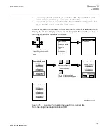
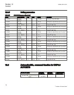
if it is used just for the monitoring, the switches will be listed with their actual
position names, as defined by the user (max. 13 characters).
•
if it is used for control, the switches will be listed with their actual positions, but
only the first three letters of the name will be used.
In both cases, the switch full name will be shown, but the user has to redefine it when
building the Graphical Display Editor, under the "Caption". If used for the control, the
following sequence of commands will ensure:
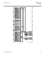
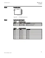
ANSI06000421-2-en.vsd
../Control/SLD/Switch
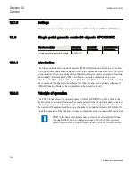
SMBRREC control
WFM
Pilot setup
OFF
Damage control
DAL
../Control/SLD/Switch
SMBRREC control
WFM
Pilot setup
OFF
P: Disc N: Disc Fe
OK Cancel
../Control/SLD/Switch
SMBRREC control
WFM
Pilot setup
OFF
Damage control
DFW
Change to the "Switches" page
of the SLD by left-right arrows.
Select switch by up-down
arrows
Control
Single Line Diagram
Commands
Control
Measurements
Events
Disturbance records
Settings
Diagnostics
Test
Reset
Authorization
Language
Select switch. Press the
Open or Close key. A
dialog box appears.
E
The pos will not be modified
(outputs will not be activated)
until
you press the E-button for O.K
.
Open
Close
ANSI06000421 V2 EN
Figure 379:
Example 2 on handling the switch from the local HMI.
From the single line diagram on local HMI.
1MRK505222-UUS C
Section 12
Control
757
Technical reference manual
Summary of Contents for Relion 670 series
Page 1: ...Relion 670 series Line differential protection RED670 ANSI Technical reference manual...
Page 2: ......
Page 40: ...34...
Page 50: ...44...
Page 60: ...54...
Page 126: ...120...
Page 384: ...378...
Page 496: ...490...
Page 556: ...550...
Page 602: ...596...
Page 620: ...614...
Page 794: ...788...
Page 864: ...858...
Page 988: ...982...
Page 998: ...992...
Page 1084: ...1078...
Page 1164: ...1158...
Page 1168: ...1162...
Page 1220: ...1214...
Page 1230: ...1224...
Page 1231: ...1225...

