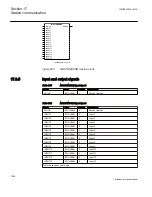
en01000134.vsd
Start
flag
Information
CRC
Stop
flag
8 bits
n x 16 bits
8 bits
16 bits
IEC01000134 V1 EN
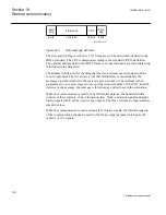
Figure 501:
Data message structure
The start and stop flags are the 0111 1110 sequence (7E hexadecimal), defined in the
HDLC standard. The CRC is designed according to the standard CRC16 definition.
The optional address field in the HDLC frame is not used instead a separate addressing
is included in the data field.
The address field is used for checking that the received message originates from the
correct equipment. There is always a risk that multiplexers occasionally mix the
messages up. Each terminal in the system is given a number. The terminal is then
programmed to accept messages from a specific terminal number. If the CRC function
detects a faulty message, the message is thrown away and not used in the evaluation.
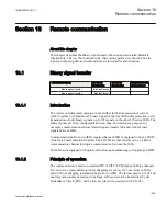
When the communication is used for line differential purpose, the transmitted data
consists of three currents, clock information, trip-, block- and alarm-signals and eight
binary signals which can be used for any purpose. The three currents are represented as
sampled values.
When the communication is used exclusively for binary signals, the full data capacity
of the communication channel is used for the binary signal purpose which gives the
capacity of 192 signals.
Section 18
1MRK505222-UUS C
Remote communication
1070
Technical reference manual
Summary of Contents for Relion 670 series
Page 1: ...Relion 670 series Line differential protection RED670 ANSI Technical reference manual...
Page 2: ......
Page 40: ...34...
Page 50: ...44...
Page 60: ...54...
Page 126: ...120...
Page 384: ...378...
Page 496: ...490...
Page 556: ...550...
Page 602: ...596...
Page 620: ...614...
Page 794: ...788...
Page 864: ...858...
Page 988: ...982...
Page 998: ...992...
Page 1084: ...1078...
Page 1164: ...1158...
Page 1168: ...1162...
Page 1220: ...1214...
Page 1230: ...1224...
Page 1231: ...1225...

