6.1.3.4
Measuring principles
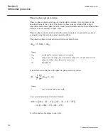
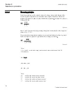
Fault loop equations use the complex values of voltage, current, and changes in the
current. Apparent impedances are calculated and compared with the set limits. The
apparent impedances at phase-to-phase faults follow equation
(example for a phase A
to phase B fault).
=
V
A
- V
B
Z
app
I
A
- I
B
EQUATION1545 V1 EN
(Equation 4)
Here V and I represent the corresponding voltage and current phasors in the respective
phase Ln (n = 1, 2, 3)
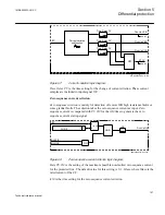
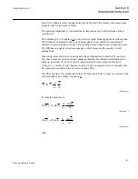
The ground return compensation applies in a conventional manner to phase-to-ground
faults (example for a phase A to ground fault) according to equation
=
+ ×
app
N
V _ A
Z
I _ A I KN
EQUATION1546 V1 EN
(Equation 5)
Where:
V_A, I_A and IN
are the phase voltage, phase current and residual current present to the IED
KN is defined as:
Z0 Z1
KN
3 Z1
-
=
×
EQUATION-2105 V1 EN
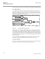
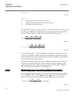
0
0
0
Z
R
jX
=
+
EQUATION2106 V1 EN
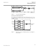
1
1
1
Z
R
jX
=
+
EQUATION2107 V1 EN
Where
R0
is setting of the resistive zero sequence reach
X0
is setting of the reactive zero sequence reach
R1
is setting of the resistive positive sequence reach
X1
is setting of the reactive positive sequence reach
Section 6
1MRK505222-UUS C
Impedance protection
180
Technical reference manual
Summary of Contents for Relion 670 series
Page 1: ...Relion 670 series Line differential protection RED670 ANSI Technical reference manual...
Page 2: ......
Page 40: ...34...
Page 50: ...44...
Page 60: ...54...
Page 126: ...120...
Page 384: ...378...
Page 496: ...490...
Page 556: ...550...
Page 602: ...596...
Page 620: ...614...
Page 794: ...788...
Page 864: ...858...
Page 988: ...982...
Page 998: ...992...
Page 1084: ...1078...
Page 1164: ...1158...
Page 1168: ...1162...
Page 1220: ...1214...
Page 1230: ...1224...
Page 1231: ...1225...

