RS485 connector pinouts
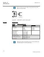
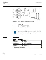
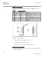
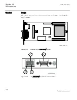
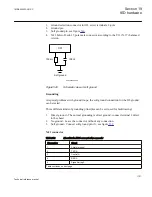
The arrangement for the pins in the RS485 connector (figure
:
Table 706:
The arrangement for the pins
Pin
Name 2-wire
Name 4-wire
Description
1
RS485+
TX+
Receive/transmit high or transmit high
2
RS485–
TX–
Receive/transmit
3
Term
T-Term
Termination resistor for transmitter (and receiver in 2–
wir case) (connect to TX+)
4
N.A.
R-Term
Termination resistor for receiver (connect to RX+)
5
N.A.
RX–
Receive low
6
N.A.
RX+
Receive high
Screw
terminal
X3
1
2
1
2
3
4
5
6
Screw
terminal
X1
Backplane
Angle
bracket
RS485
PWB
IEC06000517 V1 EN
Figure 533:
RS485 connector
•
2-wire: Connect pin 1 to pin 6 and pin 2 to pin 5
•
Termination (2-wire): Connect pin 1 to pin 3
•
Termination (4-wire): Connect pin 1 to pin 3 and pin 4 to pin 6
Soft ground connector pinouts
A second 2-pole screw connector is used for the connection of IO-ground. It can be
used in two combinations like:
Section 19
1MRK505222-UUS C
IED hardware
1120
Technical reference manual
Summary of Contents for Relion 670 series
Page 1: ...Relion 670 series Line differential protection RED670 ANSI Technical reference manual...
Page 2: ......
Page 40: ...34...
Page 50: ...44...
Page 60: ...54...
Page 126: ...120...
Page 384: ...378...
Page 496: ...490...
Page 556: ...550...
Page 602: ...596...
Page 620: ...614...
Page 794: ...788...
Page 864: ...858...
Page 988: ...982...
Page 998: ...992...
Page 1084: ...1078...
Page 1164: ...1158...
Page 1168: ...1162...
Page 1220: ...1214...
Page 1230: ...1224...
Page 1231: ...1225...

