90
95
100
0
0.5
1
en05000075_ansi.vsd
T
im
eD
ly
O
pe
ra
te
[
s]
V [% of VBase]
Exponenent
0
1
2
3
4
ANSI05000075 V1 EN
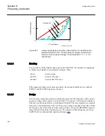
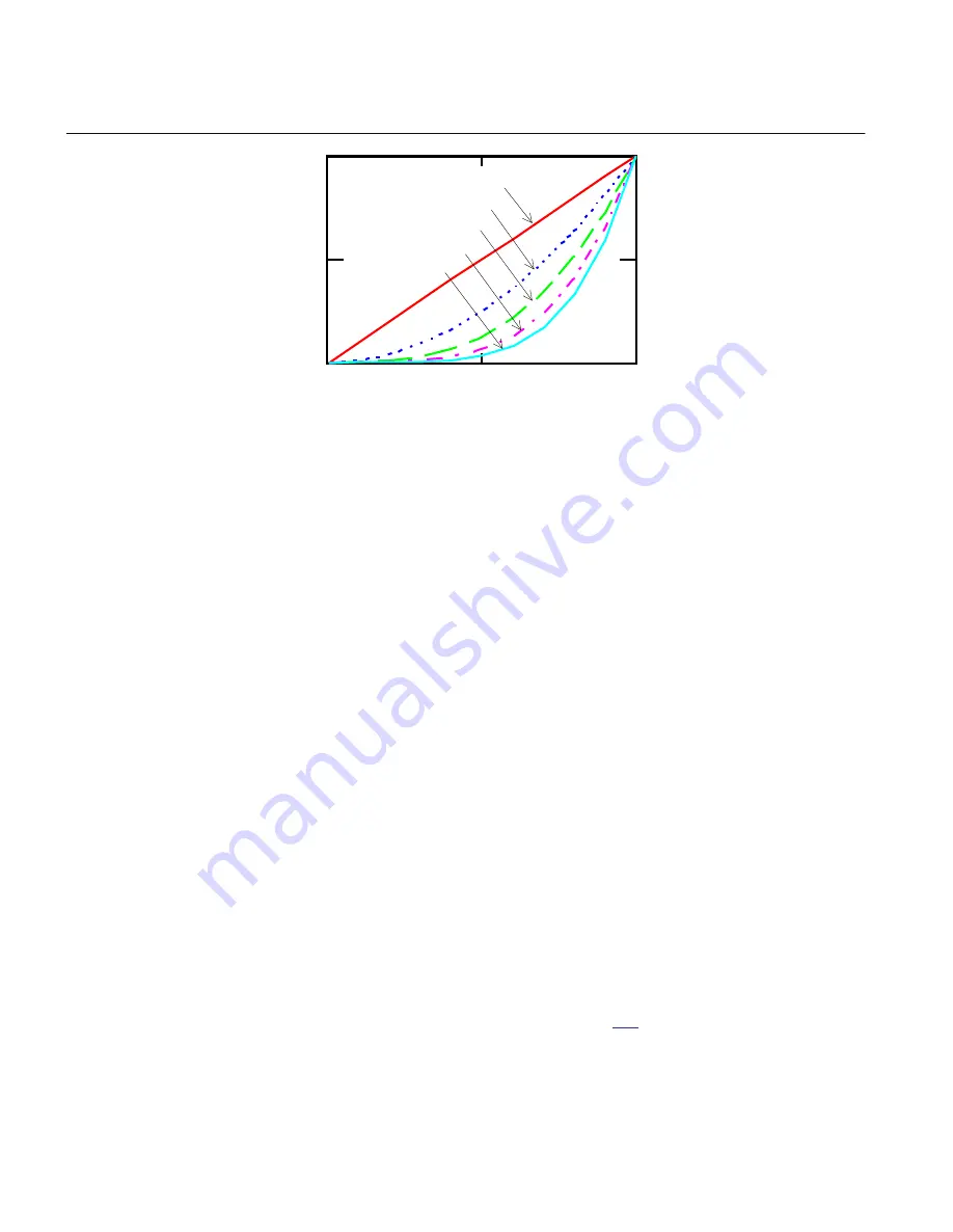
Figure 281:
Voltage dependent inverse time characteristics for underfrequency
protection SAPTUF (81). The time delay to operate is plotted as a
function of the measured voltage, for the Exponent = 0, 1, 2, 3, 4
respectively.
9.1.2.4
Blocking
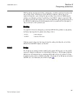
It is possible to block underfrequency protection SAPTUF (81) partially or completely,
by binary input signals or by parameter settings, where:
BLOCK:
blocks all outputs
BLKTRIP:
blocks the TRIP output
BLKREST:
blocks the RESTORE output
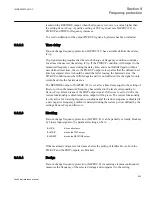
If the measured voltage level decreases below the setting of
IntBlockLevel
, both the
PICKUP and the TRIP outputs, are blocked.
9.1.2.5
Design
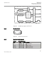
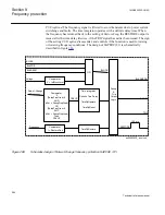
The frequency measuring element continuously measures the frequency of the positive
sequence voltage and compares it to the setting
PUFrequency
. The frequency signal is
filtered to avoid transients due to switchings and faults. The time integrator can operate
either due to a definite delay time or to the special voltage dependent delay time. When
the frequency has returned back to the setting of
RestoreFreq
, the RESTORE output is
issued after the time delay
TimeDlyRestore
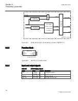
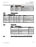
. The design of underfrequency protection
SAPTUF (81) is schematically described in figure
Section 9
1MRK505222-UUS C
Frequency protection
554
Technical reference manual
Summary of Contents for Relion 670 series
Page 1: ...Relion 670 series Line differential protection RED670 ANSI Technical reference manual...
Page 2: ......
Page 40: ...34...
Page 50: ...44...
Page 60: ...54...
Page 126: ...120...
Page 384: ...378...
Page 496: ...490...
Page 556: ...550...
Page 602: ...596...
Page 620: ...614...
Page 794: ...788...
Page 864: ...858...
Page 988: ...982...
Page 998: ...992...
Page 1084: ...1078...
Page 1164: ...1158...
Page 1168: ...1162...
Page 1220: ...1214...
Page 1230: ...1224...
Page 1231: ...1225...

