Energizing check
Voltage values are measured in the IED centrally and are available for evaluation by
the Synchronism check function.
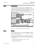
The function measures voltages on the busbar and the line to verify whether they are
live or dead. This is done by comparing with the set values
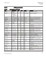
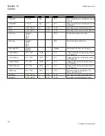
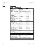
VHighBusEnerg
and
VLowBusEnerg
for bus energizing and
VHighLineEnerg
and
VLowLineEnerg
for line
energizing.
The frequency on both sides of the circuit breaker is also measured. The frequencies
must not deviate from the rated frequency more than +/-5Hz.
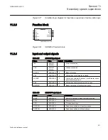
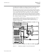
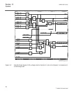
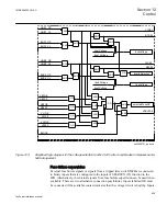
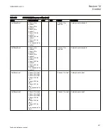
The Energizing direction can be selected individually for the Manual and the
Automatic functions respectively. When the conditions are met the outputs
AUTOENOK and MANENOK respectively will be activated if the fuse supervision
conditions are fulfilled. The output signal can be delayed independently for
MANENOK and AUTOENOK conditions. The Energizing direction can also be
selected by an integer input AENMODE respective MENMODE, which for example,
can be connected to a Binary to Integer function block (B16I). Integers supplied shall
be 1=off, 2=DLLB, 3=DBLL and 4= Both. Not connected input with connection of
INTZERO output from Fixed Signals (FIXDSIGN) function block will mean that the
setting is done from Parameter Setting tool. The active position can be read on outputs
MODEAEN resp MODEMEN. The modes are 0=OFF, 1=DLLB, 2=DBLL and 3=Both.
The inputs BLOCK and BLKENERG are available for total block of the complete
SESRSYN (25) function respective block of the Energizing check function.
TSTENERG will allow testing of the function where the fulfilled conditions are
connected to a separate test output.
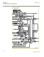
Voltage selection
The voltage selection module including supervision of included voltage transformer
fuses for the different arrangements is a basic part of the SESRSYN (25) function and
determines the parameters fed to the Synchronizing, Synchrocheck and Energizing
check functions. This includes the selection of the appropriate Line and Bus voltages
and fuse supervision.
The voltage selection type to be used is set with the parameter
CBConfig
.
If
No voltage sel.
is set the default voltages used will be V-Line1 and V-Bus1. This is
also the case when external voltage selection is provided. Fuse failure supervision for
the used inputs must also be connected.
The voltage selection function, selected voltages, and fuse conditions are the
Synchronism check and Energizing check inputs.
Section 12
1MRK505222-UUS C
Control
620
Technical reference manual
Summary of Contents for Relion 670 series
Page 1: ...Relion 670 series Line differential protection RED670 ANSI Technical reference manual...
Page 2: ......
Page 40: ...34...
Page 50: ...44...
Page 60: ...54...
Page 126: ...120...
Page 384: ...378...
Page 496: ...490...
Page 556: ...550...
Page 602: ...596...
Page 620: ...614...
Page 794: ...788...
Page 864: ...858...
Page 988: ...982...
Page 998: ...992...
Page 1084: ...1078...
Page 1164: ...1158...
Page 1168: ...1162...
Page 1220: ...1214...
Page 1230: ...1224...
Page 1231: ...1225...

