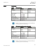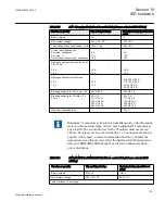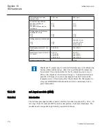
Test voltage across open
contact, 1 min
250 V rms
250 V rms
Current carrying capacity
Per relay, continuous
Per relay, 1 s
Per process connector pin,
continuous
8 A
10 A
12 A
8 A
10 A
12 A
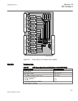
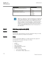
Making capacity at inductive
loadwith L/R>10 ms
0.2 s
1.0 s
30 A
10 A
0.4 A
0.4 A
Making capacity at resistive load
0.2 s
1.0 s
30 A
10 A
220–250 V/0.4 A
110–125 V/0.4 A
48–60 V/0.2 A
24–30 V/0.1 A
Breaking capacity for AC, cos
j
>0.4
250 V/8.0 A
250 V/8.0 A
Breaking capacity for DC with L/
R < 40 ms
48 V/1 A
110 V/0.4 A
220 V/0.2 A
250 V/0.15 A
48 V/1 A
110 V/0.4 A
220 V/0.2 A
250 V/0.15 A
Maximum capacitive load
-
10 nF
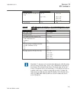
Maximum 72 outputs may be activated simultaneously with influencing
factors within nominal range. After 6 ms an additional 24 outputs may
be activated. The activation time for the 96 outputs must not exceed
200 ms. 48 outputs can be activated during 1 s. Continued activation is
possible with respect to current consumption but after 5 minutes the
temperature rise will adversely affect the hardware life. Maximum two
relays per BOM/IOM/SOM should be activated continuously due to
power dissipation.
19.2.13
mA input module (MIM)
19.2.13.1
Introduction
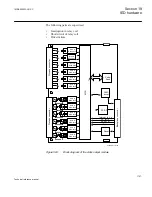
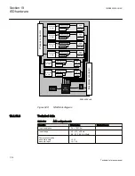
The milli-ampere input module is used to interface transducer signals in the –20 to +20
mA range from for example OLTC position, temperature or pressure transducers. The
module has six independent, galvanically separated channels.
Section 19
1MRK505222-UUS C
IED hardware
1114
Technical reference manual
Summary of Contents for Relion 670 series
Page 1: ...Relion 670 series Line differential protection RED670 ANSI Technical reference manual...
Page 2: ......
Page 40: ...34...
Page 50: ...44...
Page 60: ...54...
Page 126: ...120...
Page 384: ...378...
Page 496: ...490...
Page 556: ...550...
Page 602: ...596...
Page 620: ...614...
Page 794: ...788...
Page 864: ...858...
Page 988: ...982...
Page 998: ...992...
Page 1084: ...1078...
Page 1164: ...1158...
Page 1168: ...1162...
Page 1220: ...1214...
Page 1230: ...1224...
Page 1231: ...1225...

