

4.11.2
Principle of operation
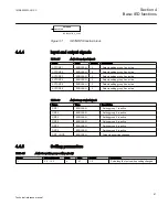
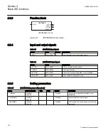
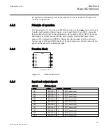
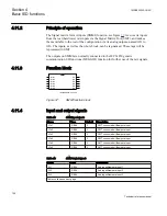
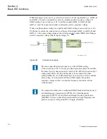
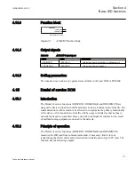
The Signal matrix for mA inputs (SMMI) function, see figure
from the real (hardware) mA inputs via the Signal Matrix Tool (SMT), and makes
them available to the rest of the configuration via its analog outputs, named AI1 to
AI6. The inputs, as well as the whole block, can be tag-named. These tags will be
represented in SMT.
The outputs on SMMI are normally connected to the IEC61850 generic
communication I/O functions (MVGGIO) function for further use of the mA signals.
4.11.3
Function block
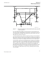
IEC05000440-2-en.vsd
SMMI
^VIN1
^VIN2
^VIN3
^VIN4
^VIN5
^VIN6
AI1
AI2
AI3
AI4
AI5
AI6
IEC05000440 V2 EN
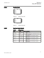
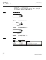
Figure 37:
SMMI function block
4.11.4
Input and output signals
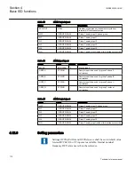
Table 42:
SMMI Input signals
Name
Type
Default
Description
VIn1
REAL
0
SMT connected milliampere input
VIn2
REAL
0
SMT connected milliampere input
VIn3
REAL
0
SMT connected milliampere input
VIn4
REAL
0
SMT connected milliampere input
VIn5
REAL
0
SMT connected milliampere input
VIn6
REAL
0
SMT connected milliampere input
Table 43:
SMMI Output signals
Name
Type
Description
AI1
REAL
Analog milliampere input 1
AI2
REAL
Analog milliampere input 2
AI3
REAL
Analog milliampere input 3
Table continues on next page
Section 4
1MRK505222-UUS C
Basic IED functions
108
Technical reference manual
Summary of Contents for Relion 670 series
Page 1: ...Relion 670 series Line differential protection RED670 ANSI Technical reference manual...
Page 2: ......
Page 40: ...34...
Page 50: ...44...
Page 60: ...54...
Page 126: ...120...
Page 384: ...378...
Page 496: ...490...
Page 556: ...550...
Page 602: ...596...
Page 620: ...614...
Page 794: ...788...
Page 864: ...858...
Page 988: ...982...
Page 998: ...992...
Page 1084: ...1078...
Page 1164: ...1158...
Page 1168: ...1162...
Page 1220: ...1214...
Page 1230: ...1224...
Page 1231: ...1225...