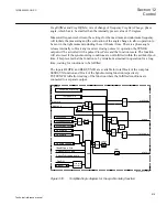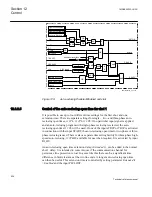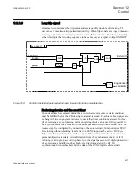
The fuse supervision is connected to VLNOK-VLNFF and with alternative Healthy or
Failing fuse signals depending on what is available from each fuse (MCB).
The tie circuit breaker is connected either to bus 1 or line 1 on one side and the other
side is connected either to bus 2 or line 2. Four different output combinations are
possible, bus to bus, bus to line, line to bus and line to line.
•
The line 1 voltage is selected if the line 1 disconnector is closed.
•
The bus 1 voltage is selected if the line 1 disconnector is open and the bus 1 circuit
breaker is closed.
•
The line 2 voltage is selected if the line 2 disconnector is closed.
•
The bus 2 voltage is selected if the line 2 disconnector is open and the bus 2 circuit
breaker is closed.
The function also checks the fuse-failure signals for bus 1, bus 2, line 1 and line 2. If a
fuse-failure is detected in the selected voltage an output signal VSELFAIL is set. This
output signal is true if the selected bus or line voltages have a fuse failure. This output
as well as the function can be blocked with the input signal BLOCK. The function
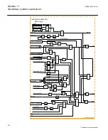
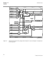
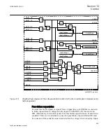
block diagram for the voltage selection of a bus circuit breaker is shown in figure
and for the tie circuit breaker in figure
1MRK505222-UUS C
Section 12
Control
623
Technical reference manual
Summary of Contents for Relion 670 series
Page 1: ...Relion 670 series Line differential protection RED670 ANSI Technical reference manual...
Page 2: ......
Page 40: ...34...
Page 50: ...44...
Page 60: ...54...
Page 126: ...120...
Page 384: ...378...
Page 496: ...490...
Page 556: ...550...
Page 602: ...596...
Page 620: ...614...
Page 794: ...788...
Page 864: ...858...
Page 988: ...982...
Page 998: ...992...
Page 1084: ...1078...
Page 1164: ...1158...
Page 1168: ...1162...
Page 1220: ...1214...
Page 1230: ...1224...
Page 1231: ...1225...

