
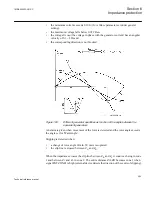


to each other can be separated with the line/s closest to the centre of the power swing
allowing the two systems to be stable as separated islands.
6.13.2
Principle of operation
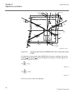
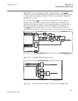
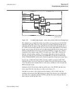
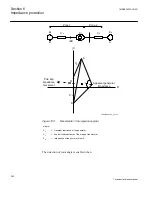
If the generator is faster than the power system, the rotor movement in the impedance
and voltage diagram is from right to left and generating is signalled. If the generator is
slower than the power system, the rotor movement is from left to right and motoring is
signalled (the power system drives the generator as if it were a motor).
The movements in the impedance plain can be seen in figure
behaviour is described by the transient EMF's E
A
and E
B
, and by X'
d
, X
T
and the
transient system impedance Z
S
.
1MRK505222-UUS C
Section 6
Impedance protection
361
Technical reference manual
Summary of Contents for Relion 670 series
Page 1: ...Relion 670 series Line differential protection RED670 ANSI Technical reference manual...
Page 2: ......
Page 40: ...34...
Page 50: ...44...
Page 60: ...54...
Page 126: ...120...
Page 384: ...378...
Page 496: ...490...
Page 556: ...550...
Page 602: ...596...
Page 620: ...614...
Page 794: ...788...
Page 864: ...858...
Page 988: ...982...
Page 998: ...992...
Page 1084: ...1078...
Page 1164: ...1158...
Page 1168: ...1162...
Page 1220: ...1214...
Page 1230: ...1224...
Page 1231: ...1225...