The Disturbance recorder acquires sampled data from selected analog- and binary
signals connected to the Disturbance report function (maximum 40 analog and 96
binary signals). The binary signals available are the same as for the event recorder
function.
The function is characterized by great flexibility and is not dependent on the operation
of protection functions. It can record disturbances not detected by protection functions.
Up to ten seconds of data before the trigger instant can be saved in the disturbance file.
The disturbance recorder information for up to 100 disturbances are saved in the IED
and the local HMI is used to view the list of recordings.
15.12.2
Principle of operation
Disturbance recording (DR) is based on the acquisition of binary and analog signals.
The binary signals can be either true binary input signals or internal logical signals
generated by the functions in the IED. The analog signals to be recorded are input
channels from the Transformer Input Module (TRM), Line Differential communication
Module (LDCM) through the Signal Matrix Analog Input (SMAI) and possible
summation (Sum3Ph) function blocks and some internally derived analog signals.For
details, refer to section
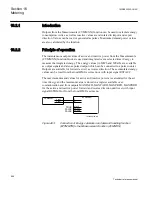
Disturbance recorder collects analog values and binary signals continuously, in a cyclic
buffer. The pre-fault buffer operates according to the FIFO principle; old data will
continuously be overwritten as new data arrives when the buffer is full. The size of this
buffer is determined by the set pre-fault recording time.
Upon detection of a fault condition (triggering), the disturbance is time tagged and the
data storage continues in a post-fault buffer. The storage process continues as long as
the fault condition prevails - plus a certain additional time. This is called the post-fault
time and it can be set in the disturbance report.
The above mentioned two parts form a disturbance recording. The whole memory,
intended for disturbance recordings, acts as a cyclic buffer and when it is full, the
oldest recording is overwritten. Up to the last 100 recordings are stored in the IED.
The time tagging refers to the activation of the trigger that starts the disturbance
recording. A recording can be trigged by, manual start, binary input and/or from analog
inputs (over-/underlevel trig).
A user-defined name for each of the signals can be set. These names are common for
all functions within the disturbance report functionality.
Section 15
1MRK505222-UUS C
Monitoring
978
Technical reference manual
Summary of Contents for Relion 670 series
Page 1: ...Relion 670 series Line differential protection RED670 ANSI Technical reference manual...
Page 2: ......
Page 40: ...34...
Page 50: ...44...
Page 60: ...54...
Page 126: ...120...
Page 384: ...378...
Page 496: ...490...
Page 556: ...550...
Page 602: ...596...
Page 620: ...614...
Page 794: ...788...
Page 864: ...858...
Page 988: ...982...
Page 998: ...992...
Page 1084: ...1078...
Page 1164: ...1158...
Page 1168: ...1162...
Page 1220: ...1214...
Page 1230: ...1224...
Page 1231: ...1225...

