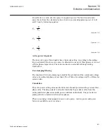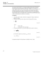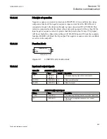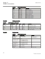
released, and in
2 out of 2
mode both the CRs should be high to release trip signal. If
any one of the channel error signals is high in
2 out of 2
mode, then logic automatically
switches to
1 out of 2
mode after a time delay of 200 ms. After switching to 1/2 mode
under channel error condition and if channel error gets cleared the mode will switch
back only after a time delay of 200 ms.
If the input channel error signal is high then the respective carrier receive signal will be
blocked.
The complete function can be blocked by setting the BLOCK input high.
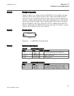
13.8.5.3
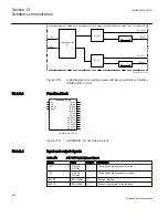
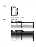
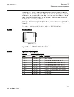
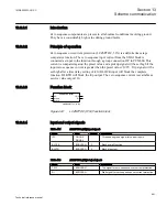
Function block
ANSI09000766-1-en.vsd
LCCRPTRC (94)
BLOCK
LOCTR
LOCTR_A
LOCTR_B
LOCTR_C
CHERR1
CHERR2
CR!
CR2
TRIP
TR_A
TR_B
TR_C
ANSI09000766 V1 EN
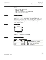
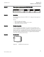
Figure 420:
LCCRPTRC (94) function block
13.8.5.4
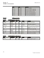
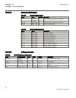
Input and output signals
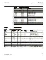
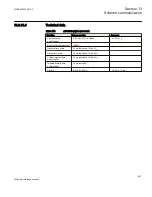
Table 463:
LCCRPTRC (94) Input signals
Name
Type
Default
Description
BLOCK
BOOLEAN
0
Block of function
LOCTR
BOOLEAN
0
Local common trip signal coming from DTT
LOCTR_A
BOOLEAN
0
Local trip signal for phase A coming from DTT
LOCTR_B
BOOLEAN
0
Local trip signal for phase B coming from DTT
LOCTR_C
BOOLEAN
0
Local trip signal for phase C coming from DTT
CHERR1
BOOLEAN
0
Channel error indication flag for carrier receive 1
CHERR2
BOOLEAN
0
Channel error indication flag for carrier receive 2
CR!
BOOLEAN
0
Carrier receive 1
CR2
BOOLEAN
0
Carrier receive 2
1MRK505222-UUS C
Section 13
Scheme communication
843
Technical reference manual
Summary of Contents for Relion 670 series
Page 1: ...Relion 670 series Line differential protection RED670 ANSI Technical reference manual...
Page 2: ......
Page 40: ...34...
Page 50: ...44...
Page 60: ...54...
Page 126: ...120...
Page 384: ...378...
Page 496: ...490...
Page 556: ...550...
Page 602: ...596...
Page 620: ...614...
Page 794: ...788...
Page 864: ...858...
Page 988: ...982...
Page 998: ...992...
Page 1084: ...1078...
Page 1164: ...1158...
Page 1168: ...1162...
Page 1220: ...1214...
Page 1230: ...1224...
Page 1231: ...1225...

