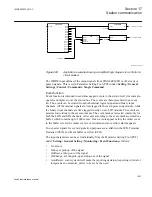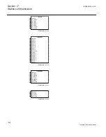
To output board, CLOSE
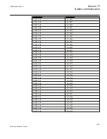
SINGLECMD
BLOCK
^OUT1
^OUT2
^OUT3
^OUT4
^OUT5
^OUT6
^OUT7
^OUT8
^OUT9
^OUT10
^OUT11
^OUT12
^OUT13
^OUT14
^OUT15
^OUT16
AND
INPUT1
INPUT2
INPUT3
INPUT4N
OUT
NOUT
PULSETIMER
INPUT
T
OUT
SYNCH OK
PULSETIMER
INPUT
T
OUT
#1.000
#1.000
To output board, OPEN
IEC05000717-2-en.vsd
IEC05000717 V2 EN
Figure 495:
Application example showing a simplified logic diagram for control of a
circuit breaker
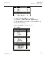
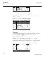
The MODE input defines if the output signals from SINGLECMD:1 is off, steady or
pulsed signals. This is set in Parameter Setting Tool (PST) under:
Setting / General
Settings / Control / Commands / Single Command
.
Event function
Event function is intended to send time-tagged events to the station level (for example,
operator workplace) over the station bus. The events are there presented in an event
list. The events can be created from both internal logical signals and binary input
channels. All the internal signals are time tagged in the main processing module, while
the binary input channels are time tagged directly on each I/O module. The events are
produced according to the set event masks. The event masks are treated commonly for
both the LON and SPA channels. All events according to the event mask are stored in a
buffer, which contains up to 1000 events. If new events appear before the oldest event
in the buffer is read, the oldest event is overwritten and an overflow alarm appears.
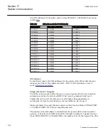
Two special signals for event registration purposes are available in the IED, Terminal
Restarted (0E50) and Event buffer overflow (0E51).
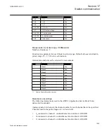
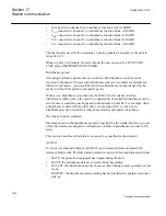
The input parameters can be set individually from the Parameter Setting Tool (PST)
under:
Setting / General Setting / Monitoring / Event Function
as follows:
•
No events
•
OnSet, at pick-up of the signal
•
OnReset, at drop-out of the signal
•
OnChange, at both pick-up and drop-out of the signal
•
AutoDetect, event system itself make the reporting decision, (reporting criteria for
integers has no semantic, prefer to be set by the user)
1MRK505222-UUS C
Section 17
Station communication
1033
Technical reference manual
Summary of Contents for Relion 670 series
Page 1: ...Relion 670 series Line differential protection RED670 ANSI Technical reference manual...
Page 2: ......
Page 40: ...34...
Page 50: ...44...
Page 60: ...54...
Page 126: ...120...
Page 384: ...378...
Page 496: ...490...
Page 556: ...550...
Page 602: ...596...
Page 620: ...614...
Page 794: ...788...
Page 864: ...858...
Page 988: ...982...
Page 998: ...992...
Page 1084: ...1078...
Page 1164: ...1158...
Page 1168: ...1162...
Page 1220: ...1214...
Page 1230: ...1224...
Page 1231: ...1225...


