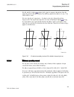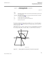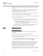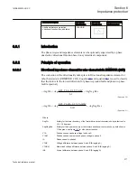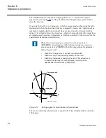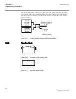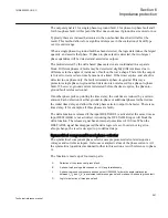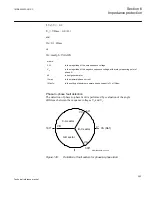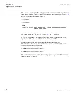
The polarizing voltage is available as long as the positive-sequence voltage exceeds
5% of the set base voltage
VBase
. So the directional element can use it for all
unsymmetrical faults including close-in faults.
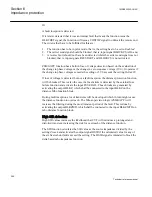
For close-in three-phase faults, the V1AM memory voltage, based on the same positive
sequence voltage, ensures correct directional discrimination.
The memory voltage is used for 100ms or until the positive sequence voltage is
restored. After 100ms, the following occurs:
•
If the current is still above the set value of the minimum operating current the
condition seals in.
•
If the fault has caused tripping, the trip endures.
•
If the fault was detected in the reverse direction, the measuring element in
the reverse direction remains in operation.
•
If the current decreases below the minimum operating value, no directional
indications will be given until the positive sequence voltage exceeds 10% of its
rated value.
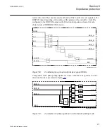
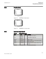
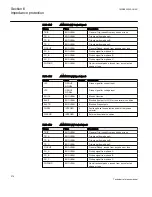
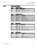
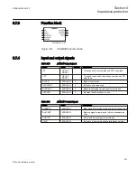
The Directional impedance element for mho characteristic (ZDMRDIR ,21D) function
has the following output signals:
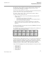
The STDIRCND output provides an integer signal that depends on the evaluation and
is derived from a binary coded signal as follows:
bit 11
(2048)
bit 10
(1024)
bit 9
(512)
bit 8
(256)
bit 7
(128)
bit 6
(64)
REV_CA1=1
REV_BC=1
REV_AB=1
REV_C=1
REV_B=1
REV_A=1
bit 5
(32)
bit 4
(16)
bit 3
(8)
bit 2
(4)
bit 1
(2)
bit 0
(1)
FWD_CA=1
FWD_BC=1
FWD_AB=1
FWD_C=1
FWD_B=1
FWD_A=1
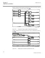
The PUFW output is a logical signal with value 1 or 0. It is made up as an OR-function
of all the forward starting conditions, that is, FWD_A, FWD_B, FWD_C, FWD_AB,
FWD_BC and RWD_CA. The PUREV output is similar to the PUFW output, the only
difference being that it is made up as an OR-function of all the reverse starting
conditions, that is, REV_A, REV_B, REV_C. REV_AB, REV_BC and REV_CA.
Values for the following parameters are calculated, and may be viewed as service values:
•
resistance phase A
•
reactance phase A
•
resistance phase B
•
reactance phase B
•
resistance phase C
1MRK505222-UUS C
Section 6
Impedance protection
279
Technical reference manual
Summary of Contents for Relion 670 series
Page 1: ...Relion 670 series Line differential protection RED670 ANSI Technical reference manual...
Page 2: ......
Page 40: ...34...
Page 50: ...44...
Page 60: ...54...
Page 126: ...120...
Page 384: ...378...
Page 496: ...490...
Page 556: ...550...
Page 602: ...596...
Page 620: ...614...
Page 794: ...788...
Page 864: ...858...
Page 988: ...982...
Page 998: ...992...
Page 1084: ...1078...
Page 1164: ...1158...
Page 1168: ...1162...
Page 1220: ...1214...
Page 1230: ...1224...
Page 1231: ...1225...

