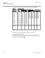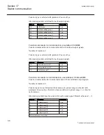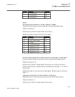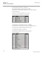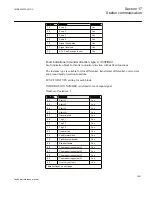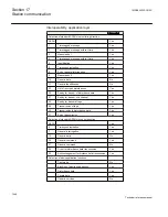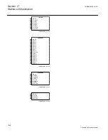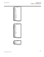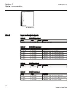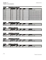
•
I
N
connected to channel 4 on disturbance function block A1RADR
•
V
AE
connected to channel 5 on disturbance function block A1RADR
•
V
BE
connected to channel 6 on disturbance function block A1RADR
•
V
CE
connected to channel 7 on disturbance function block A1RADR
•
V
EN
connected to channel 8 on disturbance function block A1RADR
Channel number used for the remaining 32 analog signals are numbers in the private
range 64 to 95.
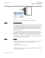
Binary signals, 96-channels: for each channel the user can specify a FUNCTION
TYPE and an INFORMATION NUMBER.
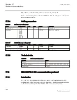
Disturbance upload
All analog and binary signals that are recorded with disturbance recorder can be
reported to the master. The last eight disturbances that are recorded are available for
transfer to the master. A successfully transferred disturbance (acknowledged by the
master) will not be reported to the master again.
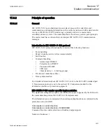
When a new disturbance is recorded by the IED a list of available recorded
disturbances will be sent to the master, an updated list of available disturbances can be
sent whenever something has happened to disturbances in this list. For example, when
a disturbance is deteceted (by other client, for example, SPA) or when a new
disturbance has been recorded or when the master has uploaded a disturbance.
Deviations from the standard
Information sent in the disturbance upload is specified by the standard; however, some
of the information are adapted to information available in disturbance recorder in 670
series.
This section describes all data that is not exactly as specified in the standard.
ASDU23
In ‘list of recorded disturbances’ (ASDU23) an information element named SOF
(status of fault) exists. This information element consists of 4 bits and indicates whether:
•
Bit TP: the protection equipment has tripped during the fault
•
Bit TM: the disturbance data are currently being transmitted
•
Bit TEST: the disturbance data have been recorded during normal operation or test
mode.
•
Bit OTEV: the disturbance data recording has been initiated by another event than
pick-up
Section 17
1MRK505222-UUS C
Station communication
1044
Technical reference manual
Summary of Contents for Relion 670 series
Page 1: ...Relion 670 series Line differential protection RED670 ANSI Technical reference manual...
Page 2: ......
Page 40: ...34...
Page 50: ...44...
Page 60: ...54...
Page 126: ...120...
Page 384: ...378...
Page 496: ...490...
Page 556: ...550...
Page 602: ...596...
Page 620: ...614...
Page 794: ...788...
Page 864: ...858...
Page 988: ...982...
Page 998: ...992...
Page 1084: ...1078...
Page 1164: ...1158...
Page 1168: ...1162...
Page 1220: ...1214...
Page 1230: ...1224...
Page 1231: ...1225...

