


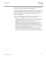
AND
AND
AND
bus1Voltage
OR
OR
OR
VL1FF
VL1OK
VB1FF
VB1OK
VB2FF
VB2OK
BUS2_CL
BUS2_OP
BUS1_CL
BUS1_OP
selectedFuseOK
BLOCK
bus2Voltage
busVoltage
AND
invalidSelection
B2SEL
B1SEL
AND
AND
AND
VSELFAIL
en05000779_ansi.vsd
OR
NOT
ANSI05000779 V1 EN
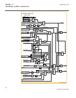
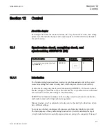
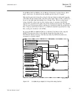
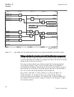
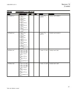
Figure 311:
Logic diagram for the voltage selection function of a single circuit breaker with double busbars
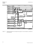
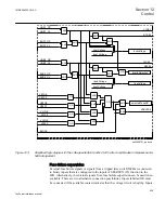
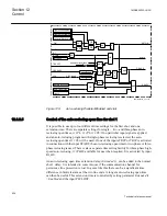
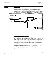
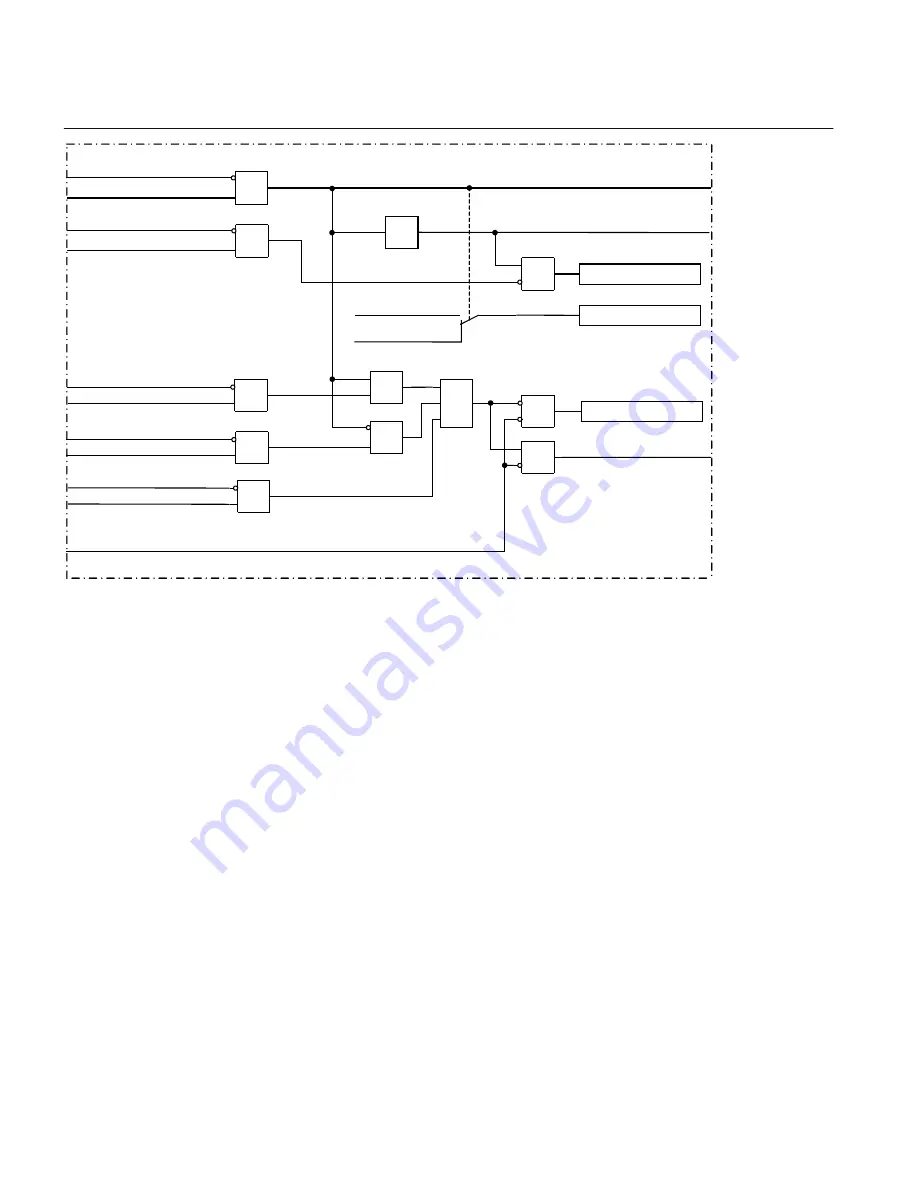
Voltage selection for a breaker-and-a-half circuit breaker arrangement
Note that with breaker-and-a-half schemes two Synchronism check functions must be
used in the IED (three for two IEDs in a complete bay). Below, the scheme for one Bus
breaker and the Tie breaker is described.
This voltage selection function uses the binary inputs from the disconnectors and
circuit breakers auxiliary contacts to select the right voltage for the SESRSYN
(Synchronism and Energizing check) function. For the bus circuit breaker one side of
the circuit breaker is connected to the busbar and the other side is connected either to
line 1, line 2 or the other busbar depending on the arrangement.
Inputs LINE1_OP-LINE1_CL, BUS1_OP-BUS1_CL, BUS2_OP-BUS2_CL,
LINE2_OP-LINE2_CL are inputs for the position of the Line disconnectors
respectively the Bus and Tie breakers. The outputs L1SEL, L2SEL and B2SEL will
give indication of the selected Line voltage as a reference to the fixed Bus 1 voltage,
which indicates B1SEL.
Section 12
1MRK505222-UUS C
Control
622
Technical reference manual
Summary of Contents for Relion 670 series
Page 1: ...Relion 670 series Line differential protection RED670 ANSI Technical reference manual...
Page 2: ......
Page 40: ...34...
Page 50: ...44...
Page 60: ...54...
Page 126: ...120...
Page 384: ...378...
Page 496: ...490...
Page 556: ...550...
Page 602: ...596...
Page 620: ...614...
Page 794: ...788...
Page 864: ...858...
Page 988: ...982...
Page 998: ...992...
Page 1084: ...1078...
Page 1164: ...1158...
Page 1168: ...1162...
Page 1220: ...1214...
Page 1230: ...1224...
Page 1231: ...1225...