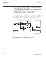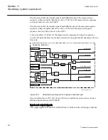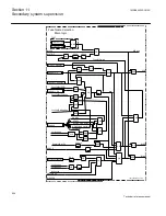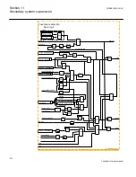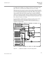
Figure 304:
Simplified logic diagram for main logic of Fuse failure function
11.2.2.2
Delta current and delta voltage detection
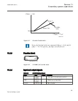
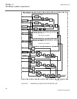
A simplified diagram for the functionality is found in figure
change is based on vector change which means that it detects both amplitude and phase
angle changes. The calculated delta quantities are compared with their respective set
values DI< and DU> and the algorithm, detects a fuse failure if a sufficient change in
voltage without a sufficient change in current is detected in each phase separately. The
following quantities are calculated in all three phases:
•
The change in voltage DU
•
The change in current DI
The internal FuseFailDetDUDI signal is activated if the following conditions are
fulfilled for a phase:
•
The magnitude of the phase-ground voltage has been above UPh> for more than
1.5 cycle
•
The magnitude of DU is higher than the corresponding setting DU>
•
The magnitude of DI is below the setting DI>
and at least one of the following conditions are fulfilled:
•
The magnitude of the phase current in the same phase is higher than the setting IPh>
•
The circuit breaker is closed (CBCLOSED = True)
The first criterion means that detection of failure in one phase together with high
current for the same phase will set the output. The measured phase current is used to
reduce the risk of false fuse failure detection. If the current on the protected line is low,
a voltage drop in the system (not caused by fuse failure) is not by certain followed by
current change and a false fuse failure might occur
The second criterion requires that the delta condition shall be fulfilled in any phase at
the same time as circuit breaker is closed. Opening circuit breaker at one end and
energizing the line from other end onto a fault could lead to wrong start of the fuse
failure function at the end with the open breaker. If this is considering to be an
important disadvantage, connect the CBCLOSED input to FALSE. In this way only the
first criterion can activate the delta function.
1MRK505222-UUS C
Section 11
Secondary system supervision
605
Technical reference manual
Summary of Contents for Relion 670 series
Page 1: ...Relion 670 series Line differential protection RED670 ANSI Technical reference manual...
Page 2: ......
Page 40: ...34...
Page 50: ...44...
Page 60: ...54...
Page 126: ...120...
Page 384: ...378...
Page 496: ...490...
Page 556: ...550...
Page 602: ...596...
Page 620: ...614...
Page 794: ...788...
Page 864: ...858...
Page 988: ...982...
Page 998: ...992...
Page 1084: ...1078...
Page 1164: ...1158...
Page 1168: ...1162...
Page 1220: ...1214...
Page 1230: ...1224...
Page 1231: ...1225...

