a
b
b>a
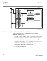
Selected current
PickupCurr_UC1
Operation_UC1=On
Bin input: BLKUC1
PU_UC1
en05000750_ansi.vsd
TRUC1
Bin input: BLKUC1TR
0-DEF
AND
AND
0
ANSI05000750 V1 EN
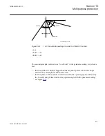
Figure 296:
Simplified internal logic diagram for built-in first undercurrent step that is, UC1 (step UC2 has the
same internal logic)
a
b
a>b
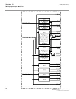
Selected voltage
PickupVolt_OV1
Operation_OV1=On
BLKOV1
Inverse time
selected
en05000751_ansi.vsd
Inverse
0-DEF
DEF time
selected
PU_OV1
TROV1
AND
BLKTROV1
AND
OR
0
ANSI05000751 V1 EN
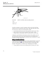
Figure 297:
Simplified internal logic diagram for built-in first overvoltage step OV1 (step OV2 has the same
internal logic)
Section 10
1MRK505222-UUS C
Multipurpose protection
582
Technical reference manual
Summary of Contents for Relion 670 series
Page 1: ...Relion 670 series Line differential protection RED670 ANSI Technical reference manual...
Page 2: ......
Page 40: ...34...
Page 50: ...44...
Page 60: ...54...
Page 126: ...120...
Page 384: ...378...
Page 496: ...490...
Page 556: ...550...
Page 602: ...596...
Page 620: ...614...
Page 794: ...788...
Page 864: ...858...
Page 988: ...982...
Page 998: ...992...
Page 1084: ...1078...
Page 1164: ...1158...
Page 1168: ...1162...
Page 1220: ...1214...
Page 1230: ...1224...
Page 1231: ...1225...

