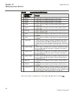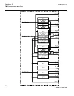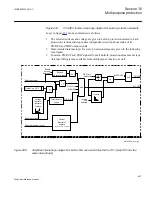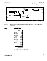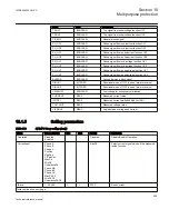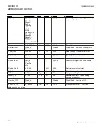
Overcurrent step simply compares the magnitude of the measured current quantity (see
table
) with the set pickup level. Non-directional overcurrent step will pickup if the
magnitude of the measured current quantity is bigger than this set level. Reset ratio is
settable, with default value of 0.96. However depending on other enabled built-in
features this overcurrent pickup might not cause the overcurrent step pickup signal.
Pickup signal will only come if all of the enabled built-in features in the overcurrent
step are fulfilled at the same time.
Second harmonic feature
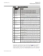
The overcurrent protection step can be restrained by a second harmonic component in
the measured current quantity (see table
). However it shall be noted that this
feature is not applicable when one of the following measured currents is selected:
•
PosSeq
(positive sequence current)
•
NegSeq
(negative sequence current)
•
UnbalancePh
(unbalance phase current)
•
UnbalancePh-Ph
(unbalance ph-ph current)
This feature will simple prevent overcurrent step pickup if the second-to-first harmonic
ratio in the measured current exceeds the set level.
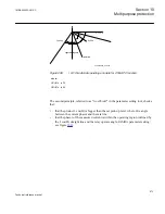
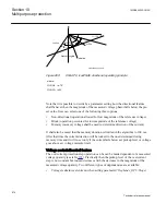
Directional feature
The overcurrent protection step operation can be can be made dependent on the
relevant phase angle between measured current phasor (see table
) and measured
). In protection terminology it means that the General
currrent and voltage protection (CVGAPC) function can be made directional by
enabling this built-in feature. In that case overcurrent protection step will only operate
if the current flow is in accordance with the set direction (
Forward
, which means
towards the protected object, or
Reverse
, which means from the protected object). For
this feature it is of the outmost importance to understand that the measured voltage
phasor (see table
) and measured current phasor (see table
directional decision. Therefore it is the sole responsibility of the end user to select the
appropriate current and voltage signals in order to get a proper directional decision.
CVGAPC function will NOT do this automatically. It will just simply use the current
and voltage phasors selected by the end user to check for the directional criteria.
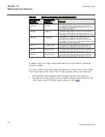
gives an overview of the typical choices (but not the only possible ones) for
these two quantities for traditional directional relays.
1MRK505222-UUS C
Section 10
Multipurpose protection
571
Technical reference manual
Summary of Contents for Relion 670 series
Page 1: ...Relion 670 series Line differential protection RED670 ANSI Technical reference manual...
Page 2: ......
Page 40: ...34...
Page 50: ...44...
Page 60: ...54...
Page 126: ...120...
Page 384: ...378...
Page 496: ...490...
Page 556: ...550...
Page 602: ...596...
Page 620: ...614...
Page 794: ...788...
Page 864: ...858...
Page 988: ...982...
Page 998: ...992...
Page 1084: ...1078...
Page 1164: ...1158...
Page 1168: ...1162...
Page 1220: ...1214...
Page 1230: ...1224...
Page 1231: ...1225...

