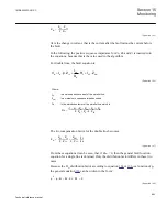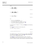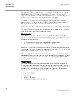
If the load compensated algorithms according to the above do not give a reliable
solution, a less accurate, non-compensated impedance model is used to calculate the
relative distance to the fault.
15.5.2.3
The non-compensated impedance model
In the non-compensated impedance model, I
A
line current is used instead of I
FA
fault
current:
A
1L
A
F
A
V
p Z
I
R I
= ×
× +
×
EQUATION1603 V1 EN
(Equation 194)
Where:
I
A
is according to table
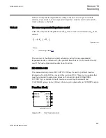
The accuracy of the distance-to-fault calculation, using the non-compensated
impedance model, is influenced by the pre-fault load current. So, this method is only
used if the load compensated models do not function.
15.5.2.4
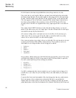
IEC 60870-5-103
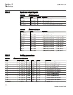
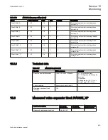
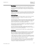
The communication protocol IEC 60870-5-103 may be used to poll fault location
information from the IED to a master (that is station HSI). There are two outputs that
must be connected to appropriate inputs on the function block I103StatFltDis,
FLTDISTX gives distance to fault (reactance, according the standard) and
CALCMADE gives a pulse (100 ms) when a result is obtainable on FLTDISTX output.
15.5.3
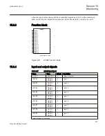
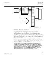
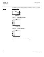
Function block
ANSI05000679-2-en.vsd
LMBRFLO
PHSEL_A*
PHSEL_B*
PHSEL_C*
CALCDIST*
FLTDISTX
CALCMADE
BCD_80
BCD_40
BCD_20
BCD_10
BCD_8
BCD_4
BCD_2
BCD_1
ANSI05000679 V2 EN
Figure 470:
FLO function block
1MRK505222-UUS C
Section 15
Monitoring
945
Technical reference manual
Summary of Contents for Relion 670 series
Page 1: ...Relion 670 series Line differential protection RED670 ANSI Technical reference manual...
Page 2: ......
Page 40: ...34...
Page 50: ...44...
Page 60: ...54...
Page 126: ...120...
Page 384: ...378...
Page 496: ...490...
Page 556: ...550...
Page 602: ...596...
Page 620: ...614...
Page 794: ...788...
Page 864: ...858...
Page 988: ...982...
Page 998: ...992...
Page 1084: ...1078...
Page 1164: ...1158...
Page 1168: ...1162...
Page 1220: ...1214...
Page 1230: ...1224...
Page 1231: ...1225...

