1.1.3.3
Input and output signals
Input and output signals are presented in two separate tables. Each table consists of two
columns. The first column contains the name of the signal and the second column
contains the description of the signal.
1.1.3.4
Function block
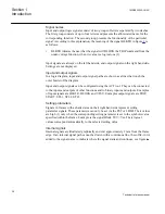
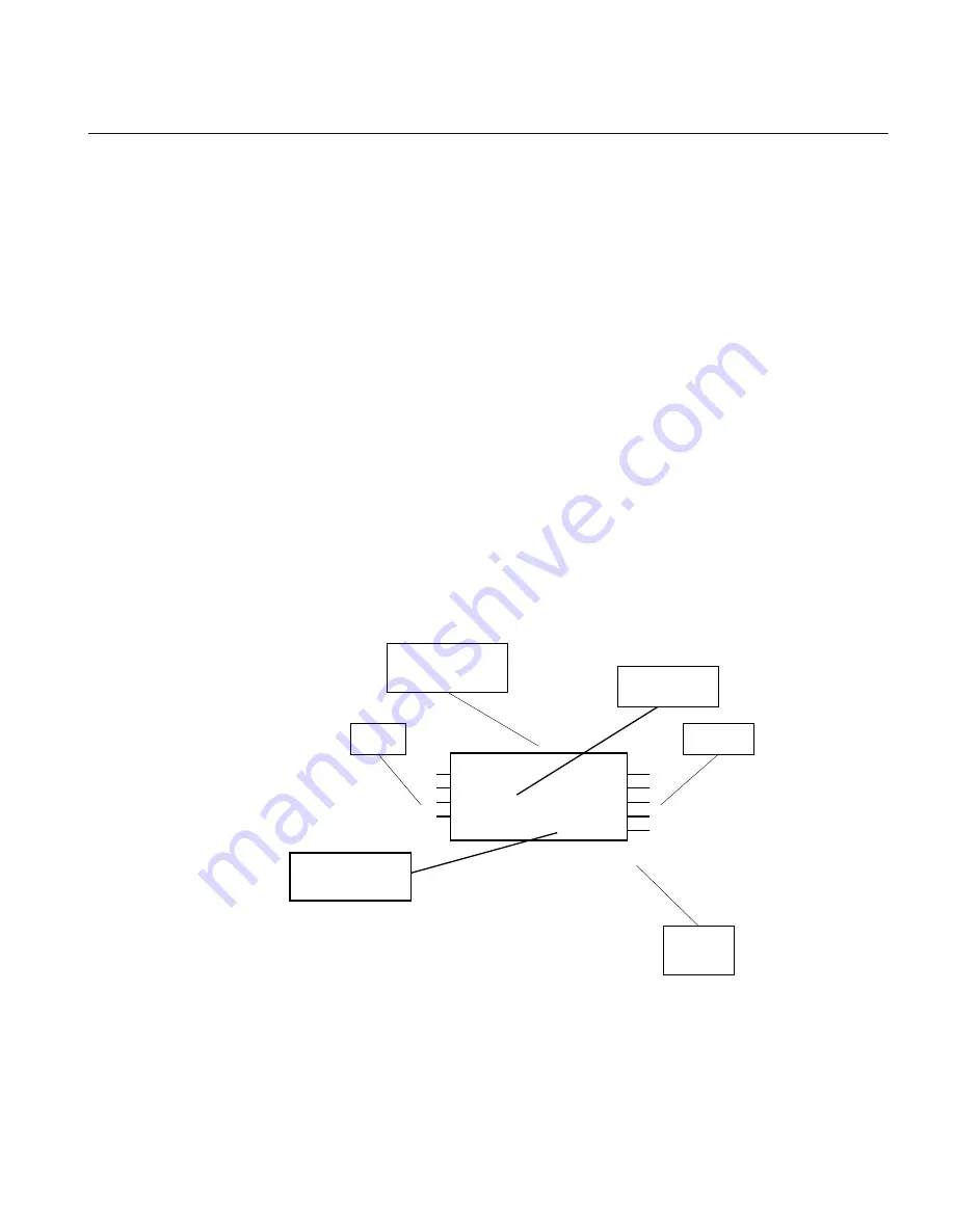
Each function block is illustrated graphically.
Input signals are always on the left hand side and output signals on the right hand side.
Settings are not displayed. Special kinds of settings are sometimes available. These are
supposed to be connected to constants in the configuration scheme and are therefore
depicted as inputs. Such signals will be found in the signal list but described in the
settings table.
•
The ^ character in front of an input or output signal name in the function block
symbol given for a function, indicates that the user can set a signal name of their
own in PCM600.
•
The * character after an input or output signal name in the function block symbol
given for a function, indicates that the signal must be connected to another
function block in the application configuration to achieve a valid application
configuration.
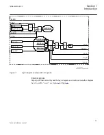
en05000511-1-en.vsd
IEC 61850 - 8 -1
Logical Node
Outputs
Inputs
Diagram
Number
Mandatory
signal (*)
PCGGIO
BLOCK
READ_VAL
BI_PULSE*
RS_CNT
INVALID
RESTART
BLOCKED
NEW_VAL
^SCAL_VAL
User defined
name (^)
IEC05000511 V2 EN
Figure 4:
Example of a function block
1MRK505222-UUS C
Section 1
Introduction
41
Technical reference manual
Summary of Contents for Relion 670 series
Page 1: ...Relion 670 series Line differential protection RED670 ANSI Technical reference manual...
Page 2: ......
Page 40: ...34...
Page 50: ...44...
Page 60: ...54...
Page 126: ...120...
Page 384: ...378...
Page 496: ...490...
Page 556: ...550...
Page 602: ...596...
Page 620: ...614...
Page 794: ...788...
Page 864: ...858...
Page 988: ...982...
Page 998: ...992...
Page 1084: ...1078...
Page 1164: ...1158...
Page 1168: ...1162...
Page 1220: ...1214...
Page 1230: ...1224...
Page 1231: ...1225...

