7.11.5
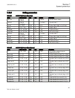
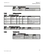
Setting parameters
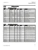
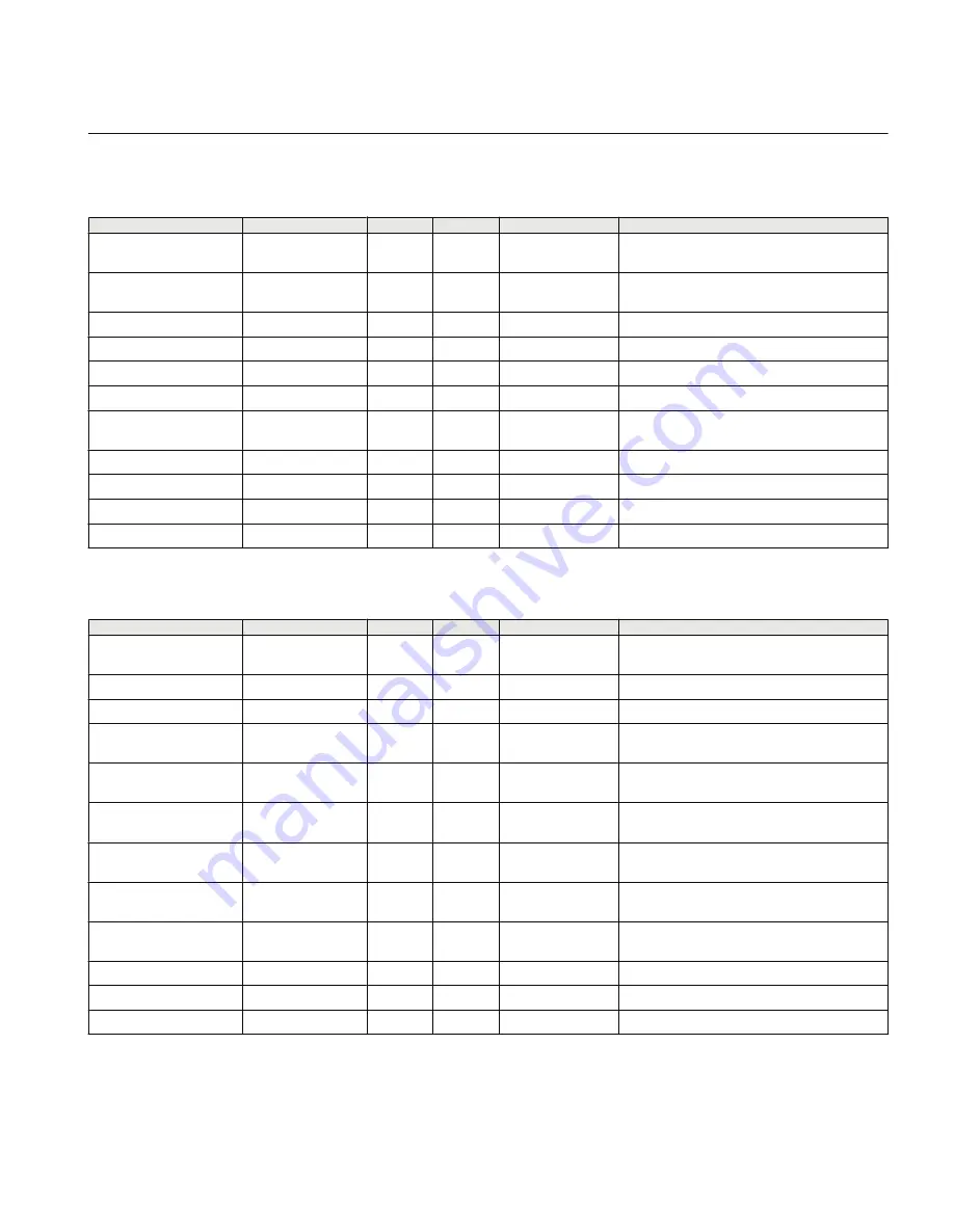
Table 236:
GUPPDUP (37) Group settings (basic)
Name
Values (Range)
Unit
Step
Default
Description
Operation
Disabled
Enabled
-
-
Disabled
Operation Disable / Enable
OpMode1
Disabled
UnderPower
-
-
UnderPower
Operation mode 1
Power1
0.0 - 500.0
%SB
0.1
1.0
Power setting for stage 1 in % of Sbase
Angle1
-180.0 - 180.0
Deg
0.1
0.0
Angle for stage 1
TripDelay1
0.010 - 6000.000
s
0.001
1.000
Trip delay for stage 1
DropDelay1
0.010 - 6000.000
s
0.001
0.060
Drop delay for stage 1
OpMode2
Disabled
UnderPower
-
-
UnderPower
Operation mode 2
Power2
0.0 - 500.0
%SB
0.1
1.0
Power setting for stage 2 in % of Sbase
Angle2
-180.0 - 180.0
Deg
0.1
0.0
Angle for stage 2
TripDelay2
0.010 - 6000.000
s
0.001
1.000
Trip delay for stage 2
DropDelay2
0.010 - 6000.000
s
0.001
0.060
Drop delay for stage 2
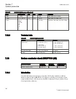
Table 237:
GUPPDUP (37) Group settings (advanced)
Name
Values (Range)
Unit
Step
Default
Description
TD
0.000 - 0.999
-
0.001
0.000
Low pass filter coefficient for power
measurement, P and Q
Hysteresis1
0.2 - 5.0
pu
0.1
0.5
Absolute hysteresis of stage 1 in % Sbase
Hysteresis2
0.2 - 5.0
pu
0.1
0.5
Absolute hysteresis of stage 2 in % Sbase
IMagComp5
-10.000 - 10.000
%
0.001
0.000
Magnitude factor to calibrate current at 5% of
In
IMagComp30
-10.000 - 10.000
%
0.001
0.000
Magnitude factor to calibrate current at 30%
of In
IMagComp100
-10.000 - 10.000
%
0.001
0.000
Magnitude factor to calibrate current at 100%
of In
VMagComp5
-10.000 - 10.000
%
0.001
0.000
Magnitude factor to calibrate voltage at 5% of
Vn
VMagComp30
-10.000 - 10.000
%
0.001
0.000
Magnitude factor to calibrate voltage at 30%
of Vn
VMagComp100
-10.000 - 10.000
%
0.001
0.000
Magnitude factor to calibrate voltage at 100%
of Vn
IAngComp5
-10.000 - 10.000
Deg
0.001
0.000
Angle calibration for current at 5% of In
IAngComp30
-10.000 - 10.000
Deg
0.001
0.000
Angle calibration for current at 30% of In
IAngComp100
-10.000 - 10.000
Deg
0.001
0.000
Angle calibration for current at 100% of In
1MRK505222-UUS C
Section 7
Current protection
477
Technical reference manual
Summary of Contents for Relion 670 series
Page 1: ...Relion 670 series Line differential protection RED670 ANSI Technical reference manual...
Page 2: ......
Page 40: ...34...
Page 50: ...44...
Page 60: ...54...
Page 126: ...120...
Page 384: ...378...
Page 496: ...490...
Page 556: ...550...
Page 602: ...596...
Page 620: ...614...
Page 794: ...788...
Page 864: ...858...
Page 988: ...982...
Page 998: ...992...
Page 1084: ...1078...
Page 1164: ...1158...
Page 1168: ...1162...
Page 1220: ...1214...
Page 1230: ...1224...
Page 1231: ...1225...

