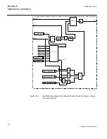
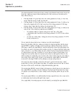

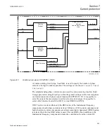
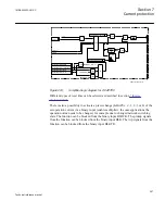

component as well as from higher current harmonic. The selected current values are
fed to OC4PTOC (51/67).
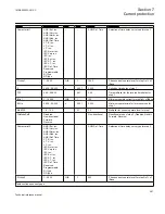
In a comparator, for each phase current, the DFT or RMS values are compared to the
set operation current value of the function
(Pickup1, Pickup2, Pickup3, Pickup4)
. If a
phase current is larger than the set operation current, outputs PICKUP, PU_STx,
PU_A, PU_B and PU_C are, without delay, activated. Output signals PU_A, PU_B
and PU_C are common for all steps. This means that the lowest set step will initiate the
activation. The PICKUP signal is common for all three phases and all steps. It shall be
noted that the selection of measured value (DFT or RMS) do not influence the
operation of directional part of OC4PTOC (51/67) .
Service value for individually measured phase currents are also available on the local
HMI for OC4PTOC (51/67) function, which simplifies testing, commissioning and in
service operational checking of the function.
A harmonic restrain of the function can be chosen. A set 2nd harmonic current in
relation to the fundamental current is used. The 2nd harmonic current is taken from the
pre-processing of the phase currents and the relation is compared to a set restrain
current level.
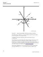
The function can be directional. The direction of the fault current is given as current
angle in relation to the voltage angle. The fault current and fault voltage for the
directional function is dependent of the fault type. To enable directional measurement
at close in faults, causing low measured voltage, the polarization voltage is a
combination of the apparent voltage (85%) and a memory voltage (15%). The
following combinations are used.
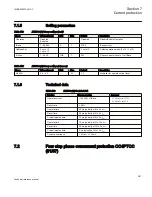
Phase-phase short circuit:
_
_
ref AB
A
B
dir AB
A
B
V
V
V
I
I
I
=
-
=
-
GUID-4F361BC7-6D91-47B5-8119-A27009C0AD6A V1 EN
(Equation 76)
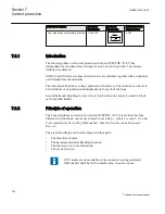
_
_
ref BC
B
C
dir BC
B
C
V
V
V
I
I
I
=
-
=
-
ANSIEQUATION1450 V1 EN
(Equation 77)
_
_
ref CA
C
A
dir CA
C
A
V
V
V
I
I
I
=
-
=
-
ANSIEQUATION1451 V1 EN
(Equation 78)
Phase-ground short circuit:
Table continues on next page
Section 7
1MRK505222-UUS C
Current protection
384
Technical reference manual
Summary of Contents for Relion 670 series
Page 1: ...Relion 670 series Line differential protection RED670 ANSI Technical reference manual...
Page 2: ......
Page 40: ...34...
Page 50: ...44...
Page 60: ...54...
Page 126: ...120...
Page 384: ...378...
Page 496: ...490...
Page 556: ...550...
Page 602: ...596...
Page 620: ...614...
Page 794: ...788...
Page 864: ...858...
Page 988: ...982...
Page 998: ...992...
Page 1084: ...1078...
Page 1164: ...1158...
Page 1168: ...1162...
Page 1220: ...1214...
Page 1230: ...1224...
Page 1231: ...1225...